BP104
© BMC Messsysteme GmbH Page 4
Important notes for using the BP104
•The BP104 is only suitable for extra-low voltages, please observe the relevant regulations!
•Only use an electrical isolated power supply unit (with CE).
•All accessible pins are electrostatic devices. Workplace must be conductive during installation.
•The construction height depends on the height of the used measuring amplifiers.
•The BP104 must only be used in closed housings (for reasons relating to EMC).
•For cleaning use water and mild detergent only.
•The device is designed to be maintenance-free. To calibrate the board it must be sent in to bmcm.
•The sensors or signals are connected at the input plug. Make sure to use shielded cables.
•For a good noise suppression connect the shield to ground at one end only. Close open inputs if possible.
•The BP104 ground is electrically connected to the next connected measuring system and therefore also to the
ground of the PC, which is usually also connected to earth. Be sure to avoid earth and ground loops during sensor
wiring, since they will cause measuring errors!
•The device must not be used for safety-relevant jobs. With the use of the product the customer becomes manufac-
turer by law and is therefore fully responsible for the proper installation and use of the product. In case of improper
use and/or unauthorized interference our warranty ceases and any warranty claim is excluded.
Do not dispose of the product in the domestic waste or at any waste collection places. It has to be either duly
disposed according to the WEEE directive or can be returned to bmcm at your own expense.
Standard measuring amplifiers available for the BP104
Order number Physical quantity to be measured Measuring range
MAL-UI voltage or current ±10V, ±5V, ±1V, ±20mA
MAL-PT100 temperature with PT100 (linearized) 0..300°C
MAL-R1K resistance 0..1kΩ
MAL-SG2 strain gauge at 5V DC excitation ±2mV/V
MAL-SG5 strain gauge at 5V DC excitation ±5mV/V
MAL-THR thermocouple type K (without linearization) 0..1250°C
MAL-ISO10 voltage ±10V
MAL-ISO5 voltage ±5V
MAL-ISO1 voltage ±1V (factory setting), ±20mA
Ex works the MAL-UI are configured in the measuring range ±10V. For MAL-THR the cold junction compensation is not realized.
Technical data BP104 (typical at 20°C)
•General
Power supply: +5V DC from the PC/104 power supply
No-load current: app. 25mA
Operating current: max. 250mA
Sensor supply: 1x +5V DC, max. 20mA, accuracy typ.: ±0.25%, TK typ.: 20ppm
Amplifier supply: app. ±12V max. 20mA
Dimensions: app. 90mm x 96mm x 25mm
Temperature range: -25°C..+70°C
Relative humidity: 0 - 90% (not condensing)
Max. permissible potentials: 60V DC acc. to VDE
CE standards: EN61000-6-1, EN61000-6-3, EN61010-1; for decl. of conformity (PDF) visit www.bmcm.de
ElektroG // ear registration: RoHS and WEEE compliant // WEEE Reg.-No. DE75472248
Accessories: miniature measuring amplifiers and converters of the MAL / MAL-ISO series,
PC/104 base board GP
Delivery: product, bolts M3 x 15mm, description
Guarantee: 2 years with effect from sales date, damages at product caused by improper use excluded
•Connections
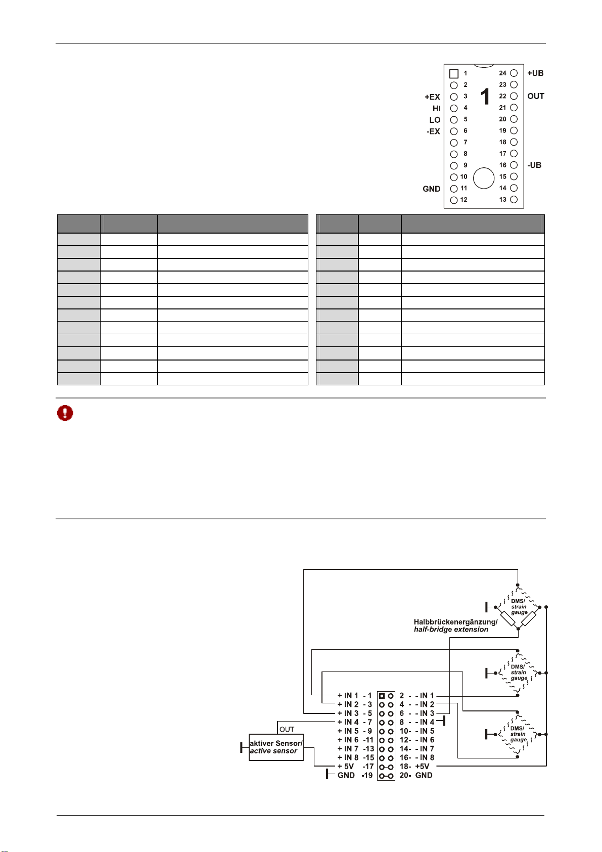
Amplifier inputs: 20-pole pin connector
Power supply: via PC/104 system plug
Amplifier outputs: 16-pole pin connector
Manufacturer: BMC Messsysteme GmbH. Subject to change due to technical improvements. Errors and printing errors excepted. Rev. 1.0 03/12/2009