BMGi TMT 400LLS Manuale utente

Copyright © 2023 BMGi. All Rights Reserved. Copyright © 2023 BMGi. All Rights Reserved.
Page 1
TMT 400LLS
SWING GATE OPENER
WITH LIMIT SWITCH AND LED INDICATOR

Copyright © 2023 BMGi. All Rights Reserved.
Page 2
Table of Contents
Important safety information .................................................................... 3 - 5
Specications & Kit inclusions ................................................................. 6 - 7
Optional Extras ............................................................................................. 8
Setup Examples ........................................................................................... 9
Before you begin.......................................................................................... 10
Solar panel .................................................................................................. 10
Important gate check ................................................................................... 11
Installation pointers...................................................................................... 12
Pull or push setup ....................................................................................... 13
Actuator arm dimension chart ..................................................................... 14
Installing gate stop & Control box ............................................................... 15
Wiring in your power option ........................................................................ 16
Battery box install.................................................................................. 17 - 18
Solar setup............................................................................................ 19 - 20
Electric setup................................................................................................ 21
Manual release............................................................................................. 22
Pull to open setup................................................................................. 23 - 26
Push to open setup............................................................................... 27 - 30
Single actuator arm wiring to main board..................................................... 31
Double actuator arm wiring to main board................................................... 32
Limit switch adjustment ....................................................................... 33 - 34
Travel Function ‘Limit Switch’ setup ........................................................... 35
Travel Function ‘Over Current’ setup .......................................................... 36
Function of LED display .............................................................................. 37
Remote tuning and delete .......................................................................... 38
Working the display screen ........................................................................ 39
Settings ............................................................................................... 40 - 44
Safety beam settings .................................................................................. 45
Accessory wiring ................................................................................. 46 - 49
Routine Maintenance ................................................................................. 50
Other Important info ................................................................................... 51

Copyright © 2023 BMGi. All Rights Reserved. Copyright © 2023 BMGi. All Rights Reserved.
Page 3
WARNING
Important Safety Information
Gate equipment has hazards associated with its use and therefore by installing this product the
installer and user accept full responsibility for following and noting the installation and safety
instructions. Failure to follow installation and safety instructions can result in hazards developing
due to improper assembly.
READ ALL INSTRUCTIONS CAREFULLY AND COMPLETELY before attempting to install and
use this automatic gate operator. This gate operator produces a high level of force. Stay clear of
the unit while it is operating and exercise caution at all times.
All safety instructions should be read and completely understood by the installer and the owner
prior to the installation of the TMT gate system. This product is designed and manufactured for
the use indicated in the manual.
Remember that all automatic gates are intended for vehicular gates only. A separate gate or
entrance must be installed for pedestrian use. Any other use, not expressly indicated may
damage the product or be a source of danger.
Swing Gate Motor - TMT 400LLS
TMT 400LLS gate motor is suitable for light - heavy gates. Do not use it on large sized gates
which exceed the maximum recommended gate weight and length nor on gates with rising hinges
or self closing hinges. Wrong selection of motor will result in an unreliable operation and will void
your warranty.
Please Read This First!
Thank you for purchasing the TMT “do-it-yourself” automatic gate opener! When correctly installed
and properly used, your TMT gate opener will give you many years of reliable service.
The TMT Opener is designed for installation on a pull-to-open or push-to-open gate and can be
used on aluminum, chain link, farm tube, wrought iron gates and timber gates.
TMT can be installed onto solid gates with a maximum size of 3.5mtrs long x 1.8mtrs high.
The Electric Gate Lock must be installed when gate are over 3.5mtrs or 40% of the gates surface
area is enclosed.
The TMT gate opener accommodates extra transmitters, digital keypads, solar panels, push
buttons, electric gate locks, and other access control products.
The TMT gate opener features an obstruction sensor. This feature makes the gate stop and
reverse when it comes in contact with an obstruction. This sensitivity can be adjusted on the main
control board.
The TMT gate opener has an adjustable auto-close feature. After the gate reaches the fully open
position, it can be set to remain open up to 300 seconds before automatically closing. Pressing the
transmitter button at any time after the gate opens fully will cause it to close immediately.
OFF is the factory setting; meaning the gate will stay open until you press the transmitter
(or keypad, etc.) again. You can adjust this in the menu settings.

Copyright © 2023 BMGi. All Rights Reserved.
Page 4
Important Safety Information
Because automatic gate operators produce high levels of force, consumers need to know the
potential hazards associated with improperly designed, installed, and maintained automated gate
opener systems. Keep in mind that the gate opener is just one component of the total gate
operating system. Each component must work in unison to provide the end user with
convenience, security, and safety.
This manual contains various safety precautions and warnings for the installer and end user.
Because there are many possible applications of the gate operator, the safety precautions and
warnings contained in this manual cannot be completely exhaustive in nature. It does, however,
provide an overview of the safe design, installation, and use of this product.
CAREFULLY READ AND FOLLOW ALL SAFETY PRECAUTIONS, WARNINGS AND
INSTALLATION INSTRUCTIONS TO ENSURE THE SAFE SYSTEM DESIGN, INSTALLATION
AND USE OF THIS PRODUCT.
Because the TMT automatic gate opener is only part of the total gate operating system, it is the
responsibility of the installer and end user to ensure that the total system is safe for its intended
use.
For the Installer and End User
1. Attach the warning sign (included) to the gate to alert the public of automatic gate operation.
2. The gate is automatic and could move at any time, posing serious risk of entrapment. No one
should be in contact with the gate when it is moving or stationary.
3. Do not attempt to drive into the gate area while the gate is moving; wait until the gate comes to
a complete stop.
4. Do not attempt to “race the gate” while the gate is closing. This is extremely dangerous.
5. Do not allow children or pets near your gate. Never let children operate or play with gate con-
trols. Keep the remote control away from children and unauthorized users; store controls where
children and unauthorized users do not have access to them.
6. KEEP GATE SYSTEM MAINTAINED. Always disconnect any power source from the operator
before performing any maintenance.
7. To operate this equipment safely, YOU must know how to disconnect the operator for manual
gate operation.
8. Disconnect the operator ONLY when all power sources are DISCONNECTED and the gate is
NOT moving.
9. Make arrangements with local re and law enforcement for emergency access.
10. Distribute and discuss copies of the IMPORTANT SAFETY INFORMATION section of this man-
ual with all persons authorized to use your gate.
11. IMPORTANT: Save these safety instructions. Make sure everyone who is using or will be
around the gate and gate operator are aware of the dangers associated with automated gate
systems. In the event you sell the property with the gate operator or sell the gate operator, pro-
vide a copy of these safety instructions to the new owner.
After Installation

Copyright © 2023 BMGi. All Rights Reserved. Copyright © 2023 BMGi. All Rights Reserved.
Page 5
To reduce the risk of injury or death:
1. READ AND FOLLOW ALL INSTRUCTIONS.
2. Never let children operate or play with gate controls. Keep the remote control away from
children.
3. Always keep people and objects away from the gate. NO ONE SHOULD CROSS THE PATH
OF THE MOVING GATE.
4. Test the gate operator monthly.
5. Use the manual/emergency release only when the gate is not moving.
6. KEEP GATES PROPERLY MAINTAINED.
7. The entrance is for vehicles only. Pedestrians must use separate entrance.
8. The gate must be installed in a location that provides adequate clearance between it and ad-
jacent structures when opening and closing to reduce the risk of entrapment. Swinging gates
must not open into public access areas.
Owner should observe the following:
1. Do not cross the gate while it is operating.
2. Keep children away from the gate and the remote controls.
3. Test the system frequently and monitor the high and low speed of the system.
4. Practice the use of the emergency release key. This is crucial in the event that the system
does not work.
5. Place the WARNING signs prominently on the gate to warn pedestrians of the automatic gate
operation on your premises. It is your responsibility to post the warning signs on both sides of
the gate.
Installer should observe the following:
1. Make sure the gate weight and length does not exceed the maximum specications.
2. The gate design must be suitable for the installation of the auto gate system.
3. Ensure that the gate is installed level and plumb and can swing freely in both directions along
the entire swing of the gate. A properly balanced swinging type gate should NOT swing open
or swing close when no pushing or pulling force is exerted onto it.
4. Control panel box must be installed in the area where it is not easily damaged.
5. Do not change with parts or components not supplied by manufacturer.
6. Make sure all wiring is correct and in accordance with electrical bylaws and in good condition
before supplying the mains power to the control panel.
7. Remove all power when doing any maintenance including solar.
8. Ensure the control panel box is free from water leakage and insects to avoid short circuiting of
the control panel. Silicon off any holes (moth balls may also help in the prevention of insects)
9. Never supply mains power directly to the DC motor
10. Transformer MUST be connected to mains power via RCD (residual current device).
11. Do not install the operating system if in doubt.
WARNING
Important Safety Information

Copyright © 2023 BMGi. All Rights Reserved.
Page 6
Technical Specications
Max gate length 5mtrs
Max gate weight 450kgs
Power Supply 240VAC down to 24VAC (50-60Hz)
Motor power supply 24Vdc
Gear type Worm gear
Peak thrust 4500N
Normal thrust 4000N
Operation stroke 540mm
Piston extension 25.5mm/sec
Opening time Dependant on opening angle and stroke used
Protection grade (IP)/ IP44
Protection class
Absorbed current (A) 5.5A for maximum 10 secs
Absorbed power (W) 144W
Manual release Key
Enclosure dimensions 1030mm * 123mm * 124mm
Kit Includes
Standard Packaging of the swing gate opener kit includes:
Single = 1 leaf Double = 2 leafs
Actuator Arm: 1 x for single or 2 x for double
Primary Post Bracket: 1 x for single or 2 x for double
Secondary Post Bracket: 1 x for single or 2 x for double
Gate Bracket: 1 x for single or 2 x for double
Rubber Gate Stop: 1 only
Release Keys: 2 only
Primary Bracket Bolts: Not supplied (Single x 4 or Double x 8)
Secondary Bracket Bolts: 2 x for single or 4 x for double
Gate Bracket Bolts: 2 x for single or 4 x for double
Securing Pins: 2 x for single or 4 x for double
Allen key: 1 only
Control Box: 1 only
Battery Box: 1 only (if solar)
Main Control Board: 1 only
Receiver: onboard
Remotes/fobs: 2
12v Battery: 2 only (if solar)
Regulator: 1 only (if Solar)
24volt 40Watt Solar Panel: 1 only (if Solar) with 10mtrs cable + mounting bracket
Transformer 24VAC 6amp: 1 only (if Electric)
Cable: 1 @ 2mtrs prewired arm cable (single kit)
1 @ 2mtrs and 1 @ 12mtrs prewired arm cable (double kit)
PLEASE NOTE:
POST BRACKET BOLTS AND CONTROL BOX MOUNTING BOLTS ARE NOT SUPPLIED
Copyright © 2023 BMGi. All Rights Reserved. Copyright © 2023 BMGi. All Rights Reserved.
Page 7
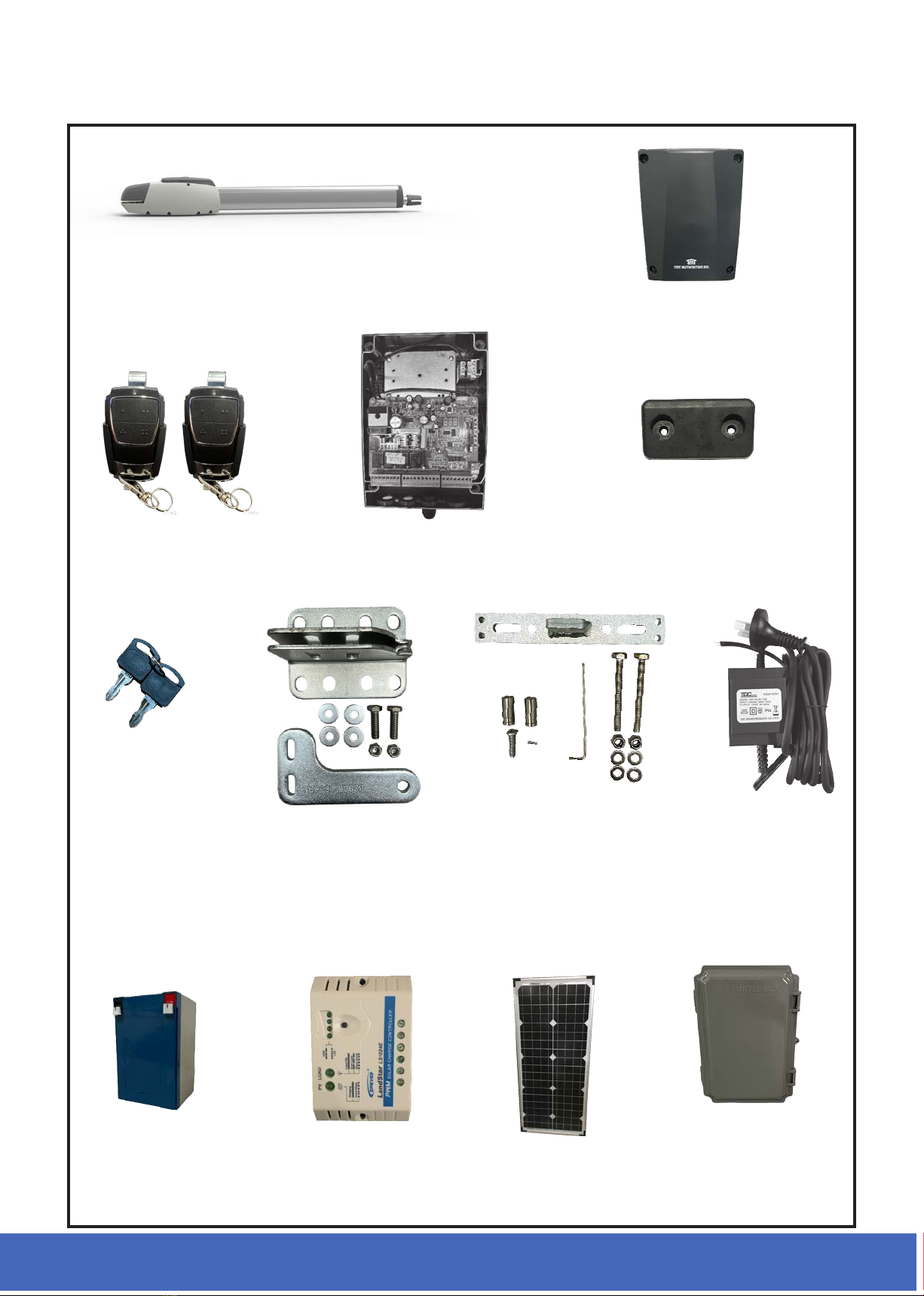
STANDARD KIT INCLUSIONS
Control Box
Actuator Arm
Main control board
Remotes Rubber stop
2 x 12v Battery
(if Solar)
Regulator
(if Solar) 24v 40watt
Solar Panel
(if Solar)
Transformer
(if Electric)
Release
keys
Battery box with
brackets (if Solar)
Post & secondary
brackets
Gate bracket
with bolts and
Arm Pins

Copyright © 2023 BMGi. All Rights Reserved.
Page 8
OPTIONAL EXTRAS
Round Post
Brackets
Round Gate Bracket
NOT CURRENTLY
AVAILABLE
Wireless Keypad Wired Keypad
Push Button
Semi wireless
Eyebeams
Keyed Push Button
(wireless or
wired available)
Long Range Receiver
Warning LIght
Electric Gate Lock
Adjustable Hinge
Scan me to see
more accessories
available

Copyright © 2023 BMGi. All Rights Reserved. Copyright © 2023 BMGi. All Rights Reserved.
Page 9
Power cable Power cable
Gate stop
(optional)
Fence post set
in concrete
Gate swing evenly and freely. Hung
rmly and plumb.
Gate bracket Actuator arm
Caution
sign
Primary bracket
Secondary bracket
Actuator arm
Cable to:
Solar panel
or
Transformer
Control box
Swing Setup Examples
Installations vary slightly on different types of gates
Gate swing evenly and freely. Hung
rmly and plumb.
Caution
sign
Control box Primary bracket
Secondary bracket
Power cable
Fence post set
in concrete
Cable to:
Solar panel
or
Transformer
Conduit
(not supplied)
Conduit
(not supplied)
Actuator arm
Gate stop
(optional)
Gate bracket
Single gate
Double gates
IMPORTANT
Be aware of the size of your gate posts and hinge position as your gates should
be no more than 100mm in from the post corner.
Refer to Actuator arm Dimension chart page 14

Copyright © 2023 BMGi. All Rights Reserved.
Page 10
Before You Begin
POWER OPTIONS
1. Transformer or solar
NEVER USE TRANSFORMER AND SOLAR PANEL(S) AT THE SAME TIME.
It will damage the control board.
IMPORTANT
Transformer is suitable for outdoor use. Use 2.5mm twin core cable (max cable run 30mtrs)
Can run solar panel cable up to 30mtrs if required for suitable lighting
Additional solar panels can be added to increase charge rate.
SOLAR PANEL
The solar panel should face full NORTH with a minimum of 6 hours of DIRECT sun exposure to be
effective (ltered sunlight not acceptable). The solar regulator supplied is not weatherproof and
must be located in the main battery box to protect it.
The performance of your gate opener is dependent on your geographical location, weather
conditions and seasonal lighting availability. On cloudy days and during winter, your solar panel
will not receive as much direct sunlight, resulting in reduced output and may reduce operating
time. Accessories connected to your system will draw additional power from the battery. It is
recommended to not use more than 1 hard wired device, such as keypad, gsm, safety beams etc.
For maximum charge see below for your area and recommended tilt:
Brisbane 38°
Sydney 45°
Melbourne 50°
Tasmania 56°
Adelaide 48°
Darwin 14°
Perth 43°
0° being at and 90° vertical
Important: just one
hand print of shade on
your solar panel can
reduce your solar
panels output by up to
80%.
Solar panel should be installed
with junction box at the top
INCORRECT CORRECT
Indice
Altri manuali BMGi Apricancello


