
body Power BRM8981 Manuale utente
For use under U.S. Patent numbers 6159132, D459773, D438264
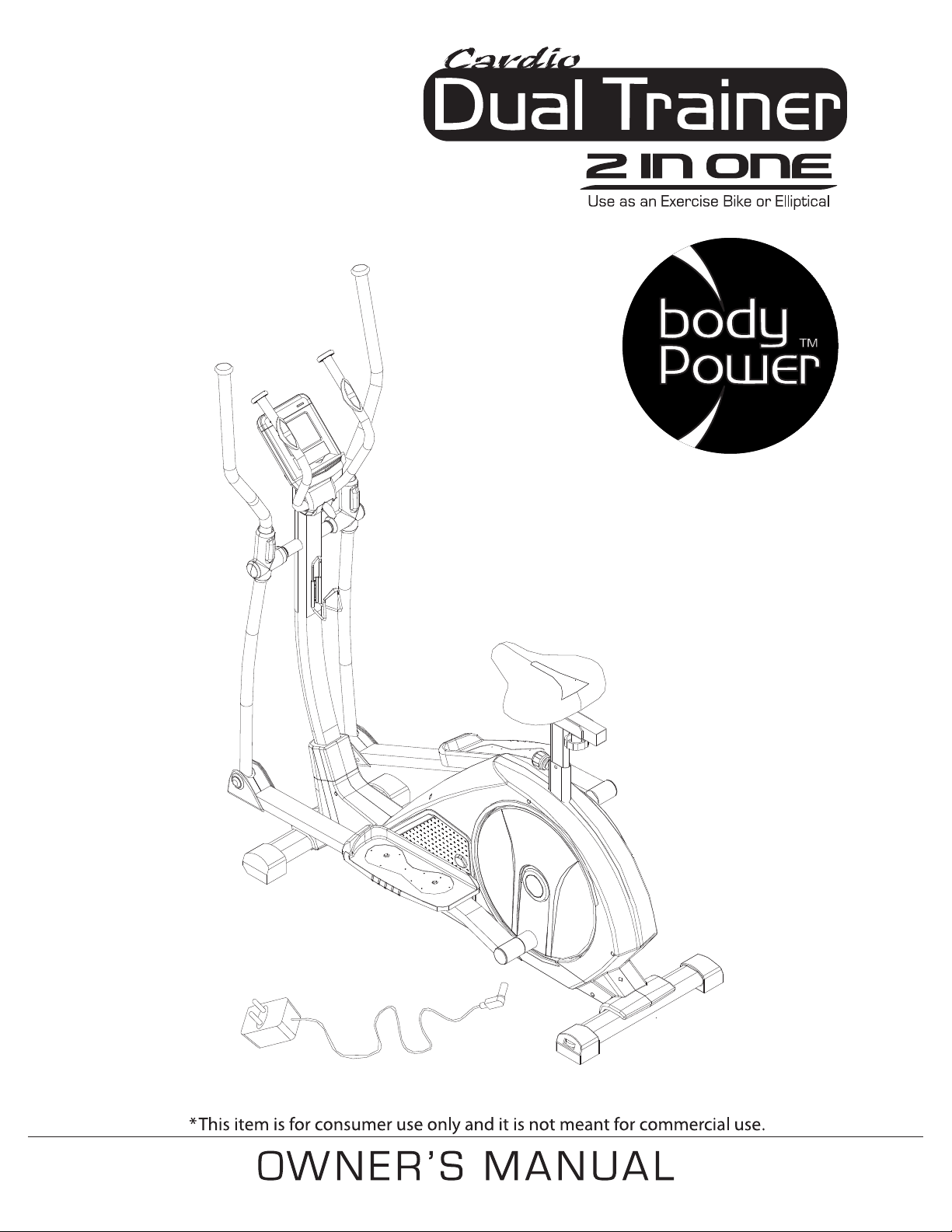
BRM8981
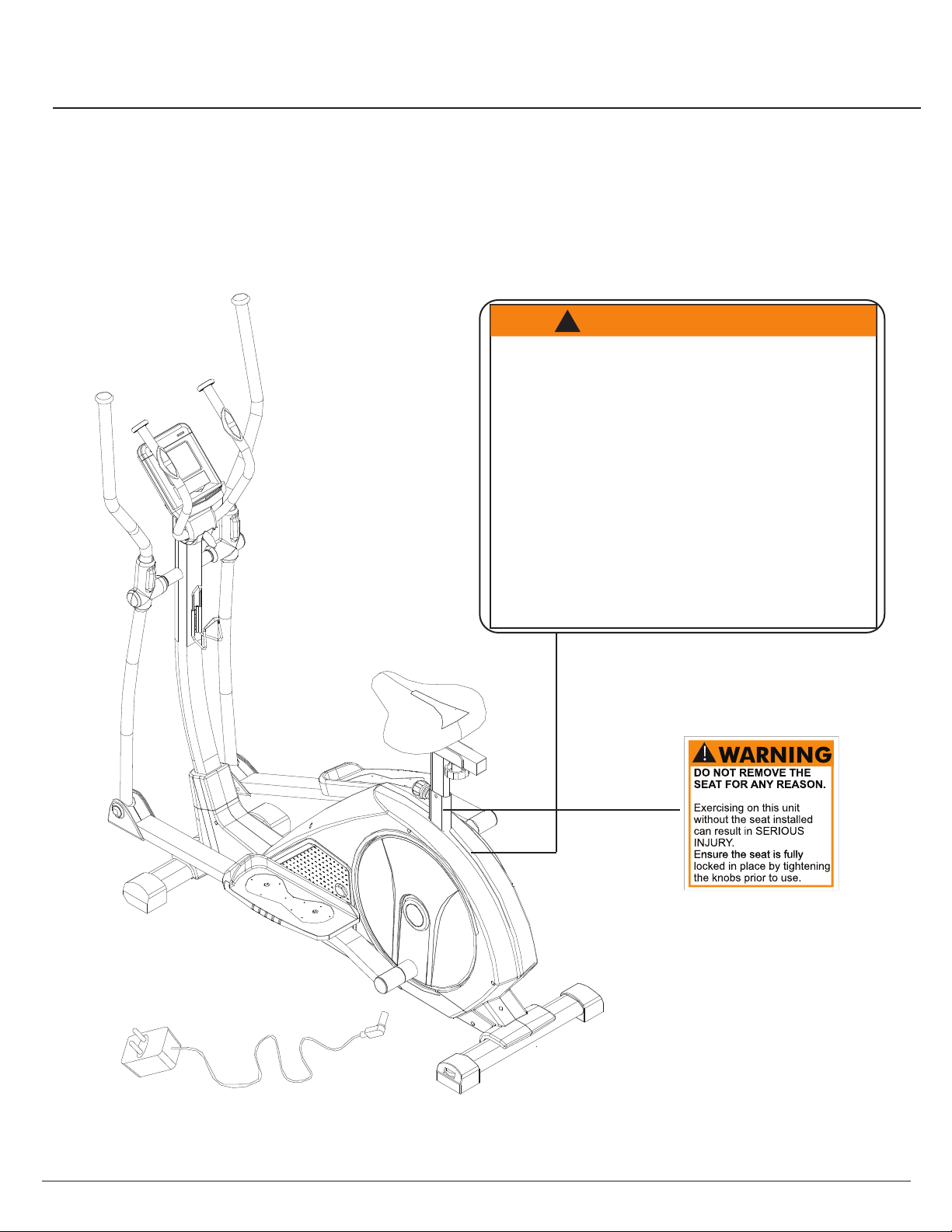
WARNING: SERIOUS INJURIES AND EVEN DEATH CAN OCCUR IF THE PROPER SAFETY PRECAUTIONS ARE NOT FOLLOWED.
The diagram below highlights and reviews many of the important Safety and Warning labels also found
on the unit. Please ensure any user of the unit familiarizes themselves with these Safety and Warning
guidelines before use.
PLEASE KEEP THESE INSTRUCTIONS FOR FUTURE USE & REFERENCE.
DO NOT DISCARD.
Page 1
BRM8981
The use of this exercise equipment involves a RISK OF PHYSICAL INJURY as well as
property damage, which can be minimized by observing the following guidelines:
1. ALWAYS wear comfortable clothing
and shoes with good traction.
2. ALWAYS make sure all nuts and bolts
are secured before use. TIGHTEN
PEDAL HINGE BOLTS EVERY 30
DAYS.
3. STOP EXERCISING if you become
dizzy, nauseous, have irregular
heartbeats or breathing difficulties.
Contact your physician immediately.
4. ALWAYS keep a large mat under the
Equipment to protect the floor or carpet.
5. ALWAYS use your Equipment in a
warm, dry, level well-lit and ventilated
indoor area.
7. ALWAYS keep your Equipment clean
and free of dust, moisture, debris and
loose objects.
8. NEVER use the Equipment if you are
injured or have a physical condition
that impairs your balance. DO NOT
exercise under the influence of
medication or alcohol.
9. NEVER allow small children or pets to
approach the Equipment. It is not a
toy.
10. NEVER use the Equipment if you
exceed its weight limit of 300 lbs.
11. NEVER use the Equipment if it does
not function properly.
6. ALWAYS keep body and clothing free
and clear of all moving parts.
W A R N I N G !
!
General Information
BRM8981
Warranty
Body Flex Sports warrants your product for
a period of 1 year for the frame and 90 days
on all parts if the item is used for the intended
purpose, properly maintained and not used
commercially. Any alterations or incorrect
assembly of the product will void this warranty.
Proof of purchase must be presented for any
warranty validation (no exceptions). This
warranty applies to the original purchaser only
and is not transferable.
This warranty does not cover abuse or defects
caused during use, storage or assembly.
During the warranty period, Body Flex Sports
reserves the right to:
a). provide replacement parts to the
purchaser in an effort to repair the item.
b). repair the product returned to our
warehouse (at the purchaser’s cost).
c). replace the product if neither of the two
previously mentioned actions effect repair.
This warranty does not cover normal wear and
tear on upholstery.
Questions
If you have any questions concerning the
assembly of your item or if any parts are
missing, please DO NOT RETURN THE
ITEM TO THE STORE OR CONTACT THE
RETAILER. Our dedicated customer service
staff can help you with any questions you may
have regarding the assembly of this unit and
can also mail you replacement parts.
Customer Support
Customer Support is open 9:00 a.m. to 5:00
p.m. (Pacific Time) Monday through Friday.
Please contact us by any of the following
means.
Body Flex Sports, Inc.
21717 Ferrero Parkway, Walnut, CA 91789
Telephone: (888) 266 - 6789
Fax: (909) 598 - 6707
Email: info@bodyflexsports.com
Safety
Before you undertake any exercise program,
please be sure to consult with your doctor.
Frequent strenuous exercise should be
approved by your doctor and proper use
of your product is essential. Excessive or incorrect
training may result to health injuries. Please read
this manual carefully before commencing the
assembly of your product or starting to exercise.
• Please keep all children away from this item
when in use. Do not allow children to climb or
play on them when they are not in use.
• Supervise teenagers while they use this unit.
• For your own safety, always ensure that there
is at least 3 feet of free space in all directions
around your product while you are exercising.
• Regularly check to see that all nuts, bolts and
fittings are securely tightened. Periodically
check all moving parts for obvious signs of
wear or damage.
• Clean only with a damp cloth, do not use
solvent cleaners. If you are in any doubt, do
not use your product; contact CUSTOMER
SUPPORT.
• Before use, always ensure that your product
is positioned on a solid, flat surface. If
necessary, use a rubber mat underneath to
reduce the possibility of slipping.
• Always wear appropriate clothing and
footwear such as training shoes when
exercising. Do not wear loose clothing that
could become caught in moving parts during
exercise.
• Do not use this unit if it is not functioning
properly or if it is not fully assembled.
• Do not use this unit for commercial purposes.
This unit is for home use only.
Storage and Use
Your product is intended for use in clean
dry conditions. You should avoid storage in
excessively cold or damp places as this may
lead to corrosion and other related problems.
Weight Limit
Your product is suitable for users weighing:
300 pounds or less.
• Before use, you must read and understand all
instructions & warnings stated in this Owner’s
Manual as well as posted on the equipment.
• It is the facility owner’s responsibility to properly
instruct users on the proper operation of the
equipment and to warn them of the potential
hazards.
• If at any time during exercise you feel faint, dizzy
or experience pain, stop and consult your
physician.
Assembling Tools
- Ruler with both metric and English measurements
- 2 x Adjustable Wrenches
- 1 x Philips (”Crosshead”) Screw Driver
•
Any adjustment devices that could interfere with
the user's movement on this unit should not be
left projecting.
Page 2

Hardware & Tool List
The following hardware is used to assemble your unit. Please take a moment to familiarize yourself with these items.
Please note, most of these parts are already pre-assembled on your unit. Do not be alarmed if you see parts on this page
that are not included in your hardware packet.
Page 3
BRM8981
Bolts
#02. Screw (M4x12 mm)
[4 Pieces]
Pre-assembled
#14. Carriage Bolt (M8x43x20xH3 mm)
[4 Pieces]
#22. Hex Bolt (M8x16xS14 mm)
[2 Pieces]
#29. Bolt (M8x16xS6 mm)
[6 Pieces]
#34. Screw (ST4.2x16Xφ8 mm)
[6 Pieces]
#35. Hex Bolt (M8x75x13xS14 mm)
[2 Pieces]
#38. Hex Bolt (M8x45x20xS14 mm)
[4 Pieces]
#51. Bolt (M8x50x20xS6 mm)
[4 Pieces]
Pre-assembled
#10. Spring Washer (d8)
[2 Pieces]
#16. Arc Washer (d8xφ20x2xR16 mm)
[4 Pieces]
#23. Washer (d8xφ32x2.0 mm)
[2 Pieces]
Washers
#30. Washer (d8xφ16x1.5 mm)
[13 Pieces]
Pre-assembled [7 Pieces]
#31. Arc Washer (d8xφ20x2xR30 mm)
[2 Pieces]
#72. Washer (d10xφ20x2.0 mm)
[1 Piece]
#74. Washer (d4xφ12x1.0 mm)
[2 Pieces]
Pre-assembled
#79. Washer (d4xФ12x1.0 mm)
[4 Pieces]
Pre-assembled
#20. Special Washer (d19xφ25x0.3 mm)
[2 Pieces]
Pre-assembled
Others
#54. Screw (ST4.2x19Xφ8 mm)
[2 Pieces]
#55. Screw (ST4.2x25Xφ8 mm)
[1 Piece]
#75. Screw (M4x12 mm)
[2 Pieces]
#39. Knob Bolt (M8xφ60x30 mm)
[4 Pieces]
#62. T Shape Bolt (M8x60x20 mm)
[1 Piece]
#63. Knob Bolt
(M16x1.5x15xφ49 mm)
[1 Piece] Pre-assembled
#66. Knob Bolt (M10xφ58x32 mm)
[1 Piece]
#45. Tool 1 (S13-14-15)
[1 Piece]
#76. Tool 2 (S13-14)
[1 Piece]
#77. Tool 3 (S6)
[1 Piece]
Pre-assembled
Nuts
#17. Nylon Nut (M8xH7.5xS13 mm) [9 Pieces] Pre-assembled [3 Pieces]

BRM 3670 Stride Cycle Page ?
Parts Listing
The following parts list describes all of the parts illustrated on the
exploded diagram on the following page. Please note, most of
these parts are already pre-assembled on your unit.
Page 4
# Description # Description
01 Monitor 40 C Shaper Washer (d40 mm)
01a Monitor Wire (Upper) 41 Bearing (2203-2RS NBK)
02 Screw (M4x12 mm) 42 Washer (d8.2xφ25x2.5 mm)
03 End Cap (φ25x22xφ52 mm) 43 Bolt (M8x20xS13 mm)
04 Hand Pulse Bar 44 Crank Cover
05 Washer (d6xφ12x1.0 mm) 45 Tool 1 (S13-14-15)
06 Screw (ST4.0x19 mm) 46L/R Left Pedal Tube Shroud (Front)
07 Hand Pulse Sensor 47L/R Main Frame Shroud 1
08 Foam (φ23x5x500 mm) 48L/R End Cap for Front Stabilizer
09 Wire Cap 49 Washer (d5xφ13x1.0 mm)
10 Spring Washer (d8) 50 Monitor Wire (Middle)
11 Crank Spacer 51 Bolt (M8x50x20xS6 mm)
12 End Cap (φ32x22xφ50 mm) 52 Rear Stabilizer
13L/R Lef/Right Handle Bar 53 End Cap for Rear Stabilizer
14 Carriage Bolt (M8x43x20xH3 mm) 54 Screw (ST4.2x19Xφ8 mm)
15 Foam (φ30x5x630 mm) 55 Screw (ST4.2x25Xφ8 mm)
16 Arc Washer (d8xφ20x2xR16 mm) 56F/R Center Post Shroud
17 Nylon Nut (M8xH7.5xS13 mm) 57 Main Frame Shroud 2
18 Front Stabilizer 58 Spacer (φ14xφ8.3x59 mm)
19 Spacer (φ32x3xφ28x21xφ19.4 mm) 59 Monitor Wire (Lower)
20 Special Washer (d19xφ25x0.3 mm) 60 Main Frame
21 Spacer (φ31.8φ19.2x54 mm) 61 Hand Pulse Wire
22 Hex Bolt (M8x16xS14 mm) 62 T Shape Bolt (M8x60x20 mm)
23 Washer (d8xφ32x2.0 mm) 63 Knob Bolt (M16x1.5x15xφ49 mm)
24 Spacer (φ32x3xφ28x16xφ14.3 mm) 64 Seat Post Sleeve
25L/R Left/Right Coupler Bar 65 Seat Post
26F/R Left Coupler Bar Shroud 66 Knob Bolt (M10xφ58x32 mm)
27F/R Right Coupler Bar Shroud 67
End Cap (
口
38 mm)
28 Center Post 68 U Bracket
29 Bolt (M8x16xS6 mm) 69 Horizontal Seat Ba
30 Washer (d8xφ16x1.5 mm) 70 Seat
31 Arc Washer (d8xφ20x2xR30 mm) 71 Ac Adapter
32 End Cap (J60X30X15 mm) 72 Washer (d10xφ20x2.0 mm)
33L/R Right Pedal Tube Shroud (Front) 73 Water Bottle Holder
34 Screw (ST4.2x16Xφ8 mm) 74 Washer (d4xφ12x1.0 mm)
35 Hex Bolt (M8x75x13xS14 mm) 75 Screw (M4x12 mm)
36L/R Left/Right Pedal Tube 76 Tool 2 (S13-14)
37L/R Left/Right Pedal 77 Tool 3 (S6)
38 Hex Bolt (M8x45x20xS14 mm) 78 Screw (ST4.2x25Xφ8 mm)
39 Knob Bolt (M8xφ60x30 mm) 79 Washer (d4xФ12x1.0 mm)
BRM8981
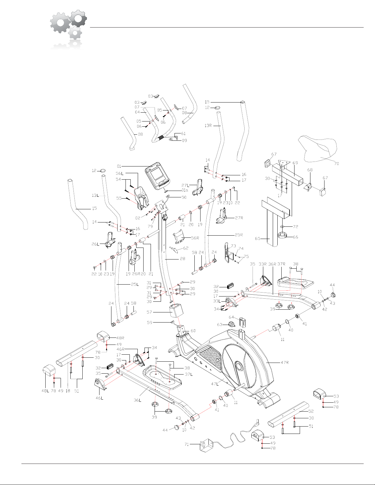
Exploded Diagram
The following diagram is provided to help you familiarize yourself with the parts and
hardware that will be used during the assembly process. Please note that not all of the
parts and hardware you see here will be used while you are assembling the machine
because some of these items are already pre-installed. Please continue to the next
page to begin the assembly process and use this page only as a reference guide for
parts and hardware.
BRM8981 Page 5

Assembly Instructions
Hardware Required
Front Rear
Please Note that the Front Stabilizer (#18) has roller
wheels that spin for ease of relocating the unit and the
Rear Stabilizer (#52) has height adjustable caps
for leveling of the unit.
Bolts
#51. Bolt (M8x50x20xS6 mm)
[4 Pieces]
Washers
#30. Washer (d8xφ16x1.5 mm)
[4 Pieces]
A s s e m b l y S t e p 1
BRM8981
With the help of an assistant, attach the Front Stabilizer
(#18) to the front of the Main Frame (#60) by inserting two
Bolts (#51) through two Washers (#30) and up through
the Front Stabilizer (#18).
Next, attach the Rear Stabilizer (#52) to the back of the Main
Frame (#60) by inserting two Bolts (#51) through two
Washers (#30) and up through the Rear Stabilizer (#52).
Remove the Bolts (#51), Washers (#30) and Tubes that
are pre-assembled on the bottom of the front and rear
of the Main Frame (#60) and set them aside. The Bolts
and Washers will be used later in this step. The two tubes
are the packing material to protect the production.
Roller Wheels
(front of caps)
Height Adjustable Caps
(bottom of caps w/
side adjustment dials)
Make sure this wire is exposed and hanging out before proceeding
to the next step. If it has fallen inside the tube, use a
bent wire to “fish” it out.
Page 6

Hardware Required
Bolts
#29. Bolt (M8x16xS6 mm)
[6 Pieces]
Washers
#30. Washer (d8xφ16x1.5 mm)
[4 Pieces]
#31. Arc Washer (d8xφ20x2xR30 mm)
[2 Pieces]
With the help of an assistant, slide the Main Frame Shroud 2
(#57) onto the Center Post (#28).
Next, connect Monitor Wire (Lower) (#59) to Monitor Wire
(Middle) (#50). Then, slip on the Center Post (#28) (with Main
Frame Shroud 2 (#57) now also attached) over the front protruding
post of the Main Frame (#60).
To attach the Center Post (#28), lift up the Main Frame Shroud 2
(#57). Secure the back of the post using two Bolts (#29) and
two Washers (#30); and then secure the front of post using two
Bolts (#29) and two Arc Washers (#31). Secure the left and right
sides using two Bolts (#29) and two Washers (#30).
You may now gently release the Main Frame Shroud 2 (#57)
(which should cover the Bolts and Washers).
B
A.
Page 7
BRM8981
Make sure this wire is hanging out before
assembling the Center post (#28).
A
A s s e m b l y S t e p 2
B.
55
40
1 2 3 4
55
40
1 2 3 4
Assembly Instructions

A s s e m b l y S t e p 3 Hardware Required
Bolts
#22. Hex Bolt (M8x16xS14 mm)
[2 Pieces]
#35. Hex Bolt (M8x75x13xS14 mm)
[2 Pieces]
#10. Spring Washer (d8)
[2 Pieces]
#23. Washer (d8xφ32x2.0 mm)
[2 Pieces]
Washers
#30. Washer (d8xφ16x1.5 mm)
[2 Pieces]
#20. Special Washer (d19xφ25x0.3 mm)
[2 Pieces]
Nuts
#17. Nylon Nut (M8xH7.5xS13 mm) [2 Pieces]
B
Page 8
BRM8981
A. Please use illustration “A” below as reference.
On the left side, ensure that one Special Washer (#20) is present (already pre-
assembled) on the Center Post (#28). (Note: Please be careful not to dispose of
Then slide on the Left Coupler Bar (#25L), followed by one Washer (#23), one
Spring Washer (#10), and secure with one Hex Bolt (#22).
On the right side, ensure that one Special Washer (#20) is present (already pre-
assembled) on the Center Post (#28).Then slide on the Right Coupler Bar
(#25R), followed by one Washer (#23), one Spring Washer (#10), and secure
with one Hex Bolt (#22).
B. Referring to close-up illustration “B”, align the holes on the Left Coupler Bar
(#25L) to the front of the Left Pedal Tube (#36L) by inserting one Hex Bolt (#35)
through the Left Pedal Tube (#36L), the Left Coupler Bar (#25L) and secure with
one Washer (#30) and one Nylon Nut (#17). Repeat this process on the right side.
AA
Special Washers (#20) when removing the protective packaging.)
Assembly Instructions
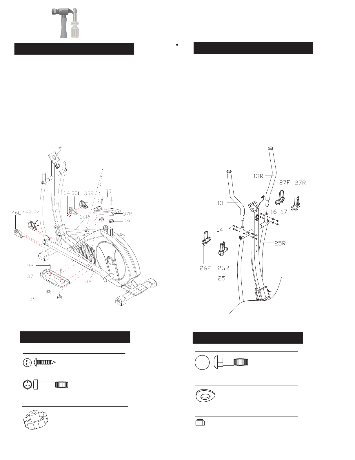
Assembly Instructions
A s s e m b l y S t e p 4
Hardware Required
Attach the Left Pedal (#37L) onto the Left Pedal Tube (#36L)
by inserting two Hex Bolts (#38) through the aligned holes*
and securing with two Knob Nuts (#39). Repeat this process
on the other side using Right Pedal (#37R).
Next, attach the Left Pedal Tube Shroud (Front) (#46L/#46R)
to the front of the Left Pedal Tube (#36L). Please make sure
the two parts are aligned and flush (you may hear the parts
gently “snapping” in place), then secure using three Screws
(#34).
On the left side, insert the Left Handle Bar (#13L) onto the
Left Coupler Bar (#25L). Align the holes and insert two
Carriage Bolts (#14) and securing with two Arc Washers
(#16) and two Nylon Nuts (#17). Repeat this process on the
other side using Right Handle Bar (#13R).
Next, attach the Left Coupler Bar Shroud (#26F/#26R)
over the assembled Left Handle Bar (#13L). Repeat this
process on the other side using the Right Coupler Bar Shroud
(#27F/#27R).
BRM8981
(Note: Please ensure the sets of selected holes match on both
sides for your safety and proper fit.)
There are 3 sets of hole options to tailor
the pedal settings to your preference.
Please ensure the same sets of holes
are selected on both sides.
Hardware Required
Page 9
Bolts
#14. Carriage Bolt (M8x43x20xH3 mm)
[4 Pieces]
#16. Arc Washer (d8xφ20x2xR16 mm)
[4 Pieces]
Washers
Nuts
#17. Nylon Nut (M8xH7.5xS13 mm) [4 Pieces]
Bolts
#34. Screw (ST4.2x16Xφ8 mm)
[6 Pieces]
#38. Hex Bolt (M8x45x20xS14 mm)
[4 Pieces]
Others
#39. Knob Bolt (M8xφ60x30 mm)
[4 Pieces]
A s s e m b l y S t e p 5
Indice
Lingue:
Altri manuali body Power Ellittica


Manuali Ellittica popolari di altre marche

Weslo
Weslo Momentum 4.0 Elliptical Manuale operativo e di manutenzione

Progear Fitness
Progear Fitness Air elliptical pro 1307 Manuale utente

Torque Fitness
Torque Fitness XPLLP Manuale utente

Octane Fitness
Octane Fitness PRO3700C Manuale utente

Xterra
Xterra FS5.8e Manuale utente

Bodyguard
Bodyguard E-40 Manuale utente

Bonn Germany
Bonn Germany Concept 2.2 Manuale utente

Precor
Precor Resolute RSL 620 Manuale utente

NordicTrack
NordicTrack E 9.2 Elliptical Manuale utente

Vision Fitness
Vision Fitness X6600iNetTV Manuale utente

Matrix
Matrix MX-A5x Manuale utente

SportsArt Fitness
SportsArt Fitness ECO-NATURAL Elite E874 Manuale utente


