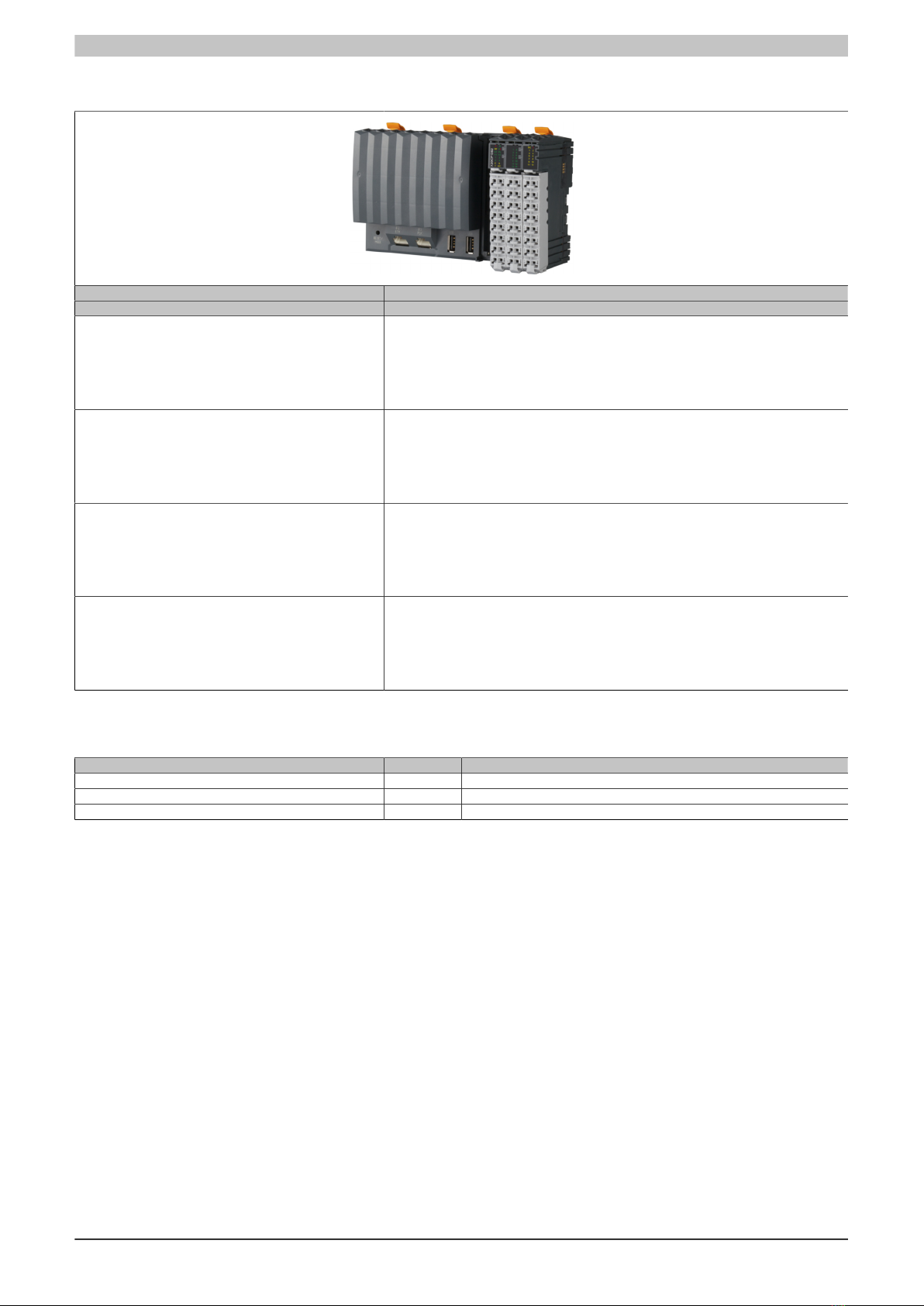
X20(c)CP1301, X20CP1381 and X20CP1382
2 Data sheet V1.21
3 Order data
Model number Short description
X20 CPUs
X20CP1301 ZX20 CPU, with integrated I/O, x86-200, 128 MB DDR3 RAM, 16 kB FRAM, 1 GB onboard flash
drive, 1 insert slot for X20 interface modules, 1 USB interface, 1 RS232 interface, 1 Ethernet
interface 10/100BASE-T, 14 digital inputs, 24 VDC, sink, 4 digital inputs, 2 µs, 24 VDC, sink, 4
digital outputs, 24 VDC, 0.5 A, source, 4 digital outputs, 2 µs, 24 VDC, 0.2 A, 4 digital inputs/out-
puts, 24 VDC, 0.5 A, 2 analog inputs ±10 V or 0 to 20 mA / 4 to 20 mA, 1 PT1000 instead of
an analog input, includes power supply module, 3x terminal block X20TB1F, slot cover and X20
end cover plate X20AC0SR1 (right) included
X20cCP1301 X20 CPU coated, with integrated I/O, x86-200, 128 MB DDR3 RAM, 16 kB FRAM, 1 GB onboard
flash drive, 1 insert slot for X20 interface modules, 1 USB interface, 1 RS232 interface, 1 Ethernet
interface 10/100BASE-T, 14 digital inputs, 24 VDC, sink, 4 digital inputs, 2 µs, 24 VDC, sink, 4
digital outputs, 24 VDC, 0.5 A, source, 4 digital outputs, 2 µs, 24 VDC, 0.2 A, 4 digital inputs/out-
puts, 24 VDC, 0.5 A, 2 analog inputs ±10 V or 0 to 20 mA / 4 to 20 mA, 1 PT1000 instead of
an analog input, includes power supply module, 3x terminal block X20TB1F, slot cover and X20
end cover plate X20AC0SR1 (right) included
X20CP1381 X20 CPU, with integrated I/O, x86-200, 128 MB DDR3 RAM, 16 kB FRAM, 1 GB onboard flash
drive, 1 insert slot for X20 interface modules, 2 USB interfaces, 1 RS232 interface, 1 CAN bus in-
terface, 1 POWERLINK interface, 1 Ethernet interface 10/100BASE-T, 14 digital inputs, 24 VDC,
sink, 4 digital inputs, 2 µs, 24 VDC, sink, 4 digital outputs, 24 VDC, 0.5 A, source, 4 digital outputs,
2 µs, 24 VDC, 0.2 A, 4 digital inputs/outputs, 24 VDC, 0.5 A, 2 analog inputs ±10 V or 0 to 20
mA / 4 to 20 mA, 1 PT1000 instead of an analog input, includes power supply module, 3x terminal
block X20TB1F, slot cover and X20 end cover plate X20AC0SR1 (right) included
X20CP1382 X20 CPU, with integrated I/O, x86-400, 256 MB DDR3 RAM, 32 kB FRAM, 2 GB onboard flash
drive, 1 insert slot for X20 interface modules, 2 USB interfaces, 1 RS232 interface, 1 CAN bus in-
terface, 1 POWERLINK interface, 1 Ethernet interface 10/100BASE-T, 14 digital inputs, 24 VDC,
sink, 4 digital inputs, 2 µs, 24 VDC, sink, 4 digital outputs, 24 VDC, 0.5 A, source, 4 digital outputs,
2 µs, 24 VDC, 0.2 A, 4 digital inputs/outputs, 24 VDC, 0.5 A, 2 analog inputs ±10 V or 0 to 20
mA / 4 to 20 mA, 1 PT1000 instead of an analog input, includes power supply module, 3x terminal
block X20TB1F, slot cover and X20 end cover plate X20AC0SR1 (right) included
Table 1: Order data
Content of delivery
Model number Quantity Short description
- 1 Interface module slot cover
X20AC0SR1 1 X20 end cover plate, right
X20TB1F 3 X20 terminal block, 16-pin, 24 VDC keyed
Table 2: Content of delivery