Bredel APEX 10 Manuale utente
Copyright © 2016 Watson-Marlow Fluid Technology Group 28-1003208
DuCoNite® and Watson-Marlow Bredel
are registered trademarks.
APEX / BREDEL PUMP
Additional information on APEX and Bredel 10, 15 and 20 pumps with bare shaft
configuration

Additional information on APEX and Bredel
10, 15 and 20 pumps with bare shaft configuration
Original Instructions

© 2017 Watson-Marlow Bredel B.V.
All rights reserved.
The information provided herein may not be reproduced and/or published in any form,
by print, photoprint, microfilm or any other means whatsoever (electronically or
mechanically) without the prior written authorisation of Watson-Marlow Bredel B.V.
The information provided can be changed without prior notification. Watson-Marlow
Bredel B.V. or one of its representatives cannot be held liable for possible damage
resulting from use of this manual. This is an extensive limitation of the liability which
applies to all damage, inclusive of (without limitation) compensating, direct, indirect or
consequential damage, loss of data, income or profit, loss or damage to possessions
and claims of third parties.
Watson-Marlow Bredel B.V. provides the information in this manual "as is" and does not
take any responsibility and does not give any guarantee on this manual or its content.
Watson-Marlow Bredel B.V. rejects all responsibilities and guarantees. Furthermore,
Watson-Marlow Bredel B.V. does not take responsibility for and does not guarantee that
the information in this manual is accurate, complete or up to date.
Names, trade names, brands, etc. used by Watson-Marlow Bredel B.V. may not, as per
the legislation concerning the protection of trade names, be considered as available.

1
CONTENTS
1 GENERAL
1.1 How to use this Manual .......................................................................... 2
1.2 Service and Support ............................................................................... 2
1.3 Used Products and the Environment ...................................................... 3
1.4 Symbols .................................................................................................. 3
1.5 Intended Use and Remarks on Safety .................................................... 3
1.6 Warranty Conditions ............................................................................... 4
2 DESCRIPTION
3 INSTALLATION
3.1 Unpacking and Inspection ...................................................................... 6
3.2 Installation .............................................................................................. 6
3.2.1 Mounting the support set and Bare Shaft Kit ............................... 7
3.2.2 Mounting and aligning the Drive .................................................. 9
4 MAINTENANCE
4.1 Cleaning ................................................................................................ 12
4.2 Demounting the Drive ........................................................................... 12
4.3 Demounting the Bare Shaft Kit ............................................................. 13
4.4 Disassembling the Bare Shaft Kit ......................................................... 14
4.5 Assembling the Bare Shaft Kit .............................................................. 15
4.6 Mounting the Bare Shaft Kit onto the Pump ......................................... 17
4.7 Mounting the Drive ................................................................................ 18
5 TROUBLESHOOTING
6 SPECIFICATIONS
6.1 Parts list ................................................................................................ 22
6.1.1 Support Set 10-20 ..................................................................... 22
6.1.2 Bare Shaft Kit ............................................................................ 23
6.2 Weights ................................................................................................. 23
6.3 Torque .................................................................................................. 24
6.4 Coupling ................................................................................................ 24
SAFETY FORM

GENERAL
2
1 GENERAL
1.1 How to use this Manual
This manual is intended as a reference book for
qualified users, enabling them to install, commission
and maintain the bare shaft set as mentioned on the
front cover. This manual is an addition to the pumphead
manual, drive manual and gearbox manual. This
manual does not replace any of these documents. The
user should carefully read these documents before
using this manual.
Documentation of components such as pumps, motors
and inverters is normally not included in this manual.
However, if additional documentation is supplied, you
must follow the instructions in this additional
documentation.
1.2 Service and Support
For information with respect to specific adjustments,
installation, maintenance or repair jobs which fall
beyond the scope of this manual, contact your Bredel
representative. Make sure you have the following data
at hand:
•
Type and / or serial number of the hose pump.
•
Description of the drive or gearbox.
You will find these data on the identification plates or
stickers of the pumphead and the drive or gearbox.
GENERAL
3
1.3 Used Products and the Environment
Enquire with your local government about the
possibilities for reuse or environment friendly
processing of packaging materials, (contaminated)
lubricant and oil.
1.4 Symbols
In this manual the following symbols are used:
1.5 Intended Use and Remarks on Safety
The bare shaft set is exclusively designed for
supporting a Bredel or an APEX pumphead and a drive.
Every other use is not in conformance with the intended
ENVIRONMENT
Always observe the local rules and
regulations with respect to processing
(nonreusable) parts of the hose pump.
WARNING
Procedures which, if not carried out with
the necessary care, may result in serious
bodily harm.
CAUTION
Procedures which, if not carried out with
the necessary care, may result in serious
damage to the hose pump, the surrounding
area or the environment.
Remarks, suggestions and advice.

GENERAL
4
use. Refer to the manual of the pumphead for more
information on safety and the intended use of the
complete pump.
1.6 Warranty Conditions
Refer to the manual of the pumphead for warranty
conditions. These conditions are applicable to the bare
shaft set as well. Damaged parts of the bare shaft set
that are returned to the manufacturer must be
accompanied by a fully filled in and signed safety form
that can be found in the manual of the pumphead.
DESCRIPTION
5
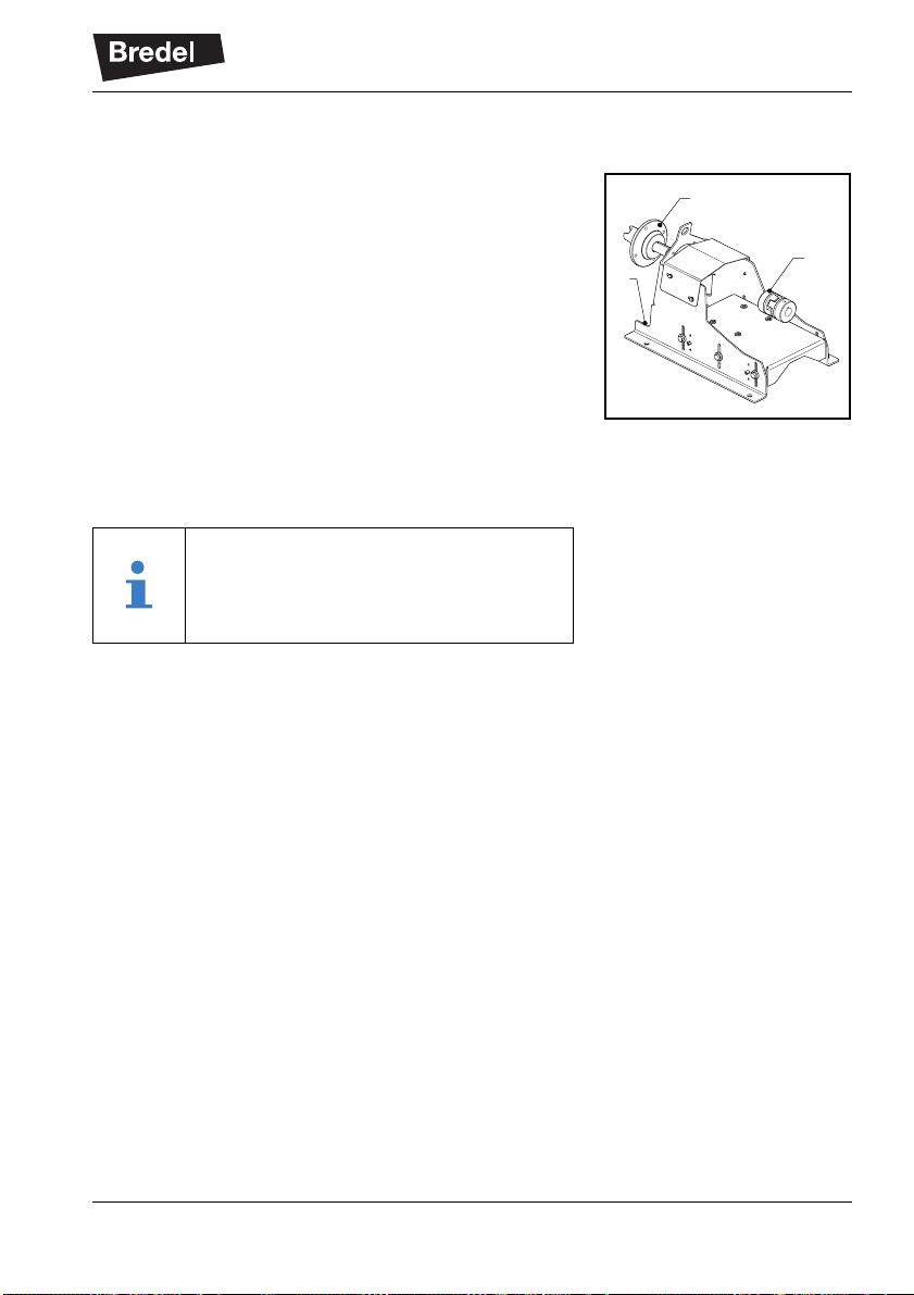
2 DESCRIPTION
The bare shaft set, if delivered separately, consists of a
support set (A) and a bare shaft kit (B). These two
components are packed separately. If the set is
delivered in a complete pump with pumphead and drive
a flexible coupling (C) is included.
The support set consists of a frame, an adjustable drive
support plate and a coupling guard.
The bare shaft kit consists of a shaft, a hub, a bearing
and a seal. No fasteners are provided for mounting the
drive or gearbox.
To align the pump and the drive use alignment jigs. The
jigs are not included in the package.
B
C
A
Although the instructions in this manual are
demonstrated with the Bredel 10-20 pump
series, these are also applicable to the
APEX10-20 series.
INSTALLATION
6
3 INSTALLATION
3.1 Unpacking and Inspection
Follow the unpacking instructions on the packaging.
Check that your delivery is correct and does not have
transport damage. Report any damage immediately to
your Bredel representative.
This chapter describes the installation of the bare shaft
set. Refer to the manual of the pumphead for
installation and setup of the complete pump and the
pipework.
3.2 Installation
CAUTION
The drive or gearbox and the pump must
be aligned within the misalignment limits of
the flexible coupling.
Carry out the alignment of the drive or
gearbox and the pump at the pump’s final
operating position. If the support set has to
be bolted to the floor this must be done
first.
A movement of the complete pump can
disturb the alignment due to elasticity of
the construction.
If the bare shaft set is delivered as part of a
complete pump, including pumphead and
drive, a realignment must be done at the
pump’s final operating position.
INSTALLATION
7
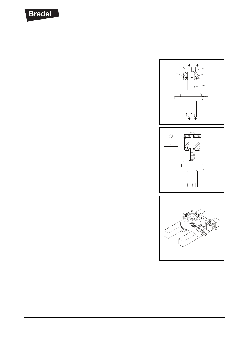
3.2.1 Mounting the support set and Bare Shaft Kit
For mounting the kit to the pumphead, the pump must
not be part of a process line and must be free of
lubricant.
1. Place the bare shaft kit (A) on a flat surface with
the key end upward.
Press coupling half (B) onto the shaft end until
shaft end face (C) and coupling surface (D) are
at equal level.
Slightly fasten screw (E).
Prevent unnecessary axial load on the bearing.
Alternative method of pressing the coupling half
onto the shaft end is using a threaded rod
screwed into the threaded hole in the shaft end,
a disc with hole and a nut. Turning the nut will
drive the coupling half onto the shaft.
This way the coupling half can be mounted after
the placement of the bare shaft kit on the
pumphead.
2. Use a hoist to place the pumphead with the
cover side on blocks.
D
B
C
A
E
Questo manuale è adatto per i seguenti modelli
2
Indice
Altri manuali Bredel Pompa dell'acqua


Manuali Pompa dell'acqua popolari di altre marche


Sykes AmeriPumps
Sykes AmeriPumps GP100M Guida alla risoluzione dei problemi

DUROMAX
DUROMAX XP WX Series Manuale utente

BRINKMANN PUMPS
BRINKMANN PUMPS SBF550 Manuale utente

Franklin Electric
Franklin Electric IPS Manuale utente

Xylem
Xylem e-1532 Series Manuale utente

Milton Roy
Milton Roy PRIMEROYAL Manuale utente