DRAIN SIGNAL DELAY PROGRAM
The cooler will periodically drain itself of water in order to ensure clean operating conditions.
When it does, it sends a signal allowing a scavenger pump or other control to begin operating
(terminal J7-4). The drain delay feature allows time for the drained water to travel from the cooler
to the scavenger pump before the scavenger pump begins to operate.
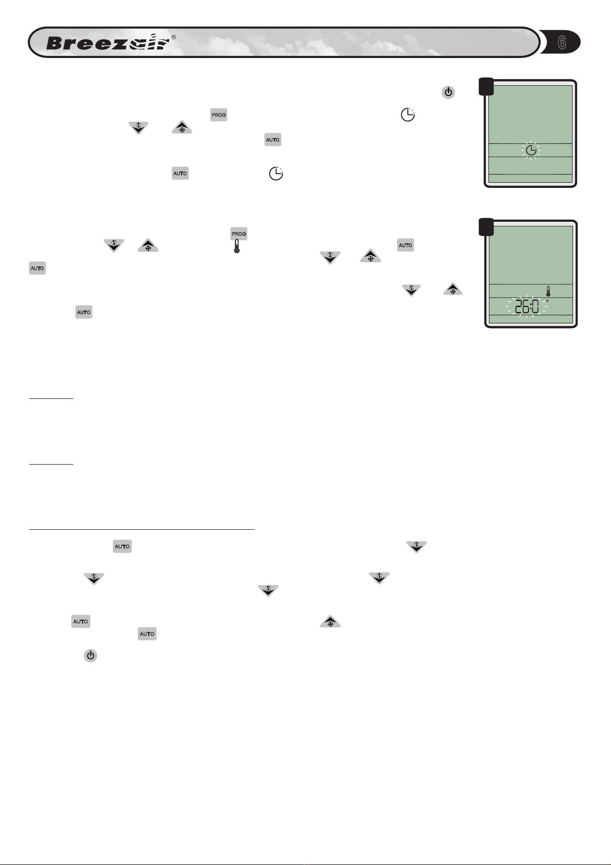
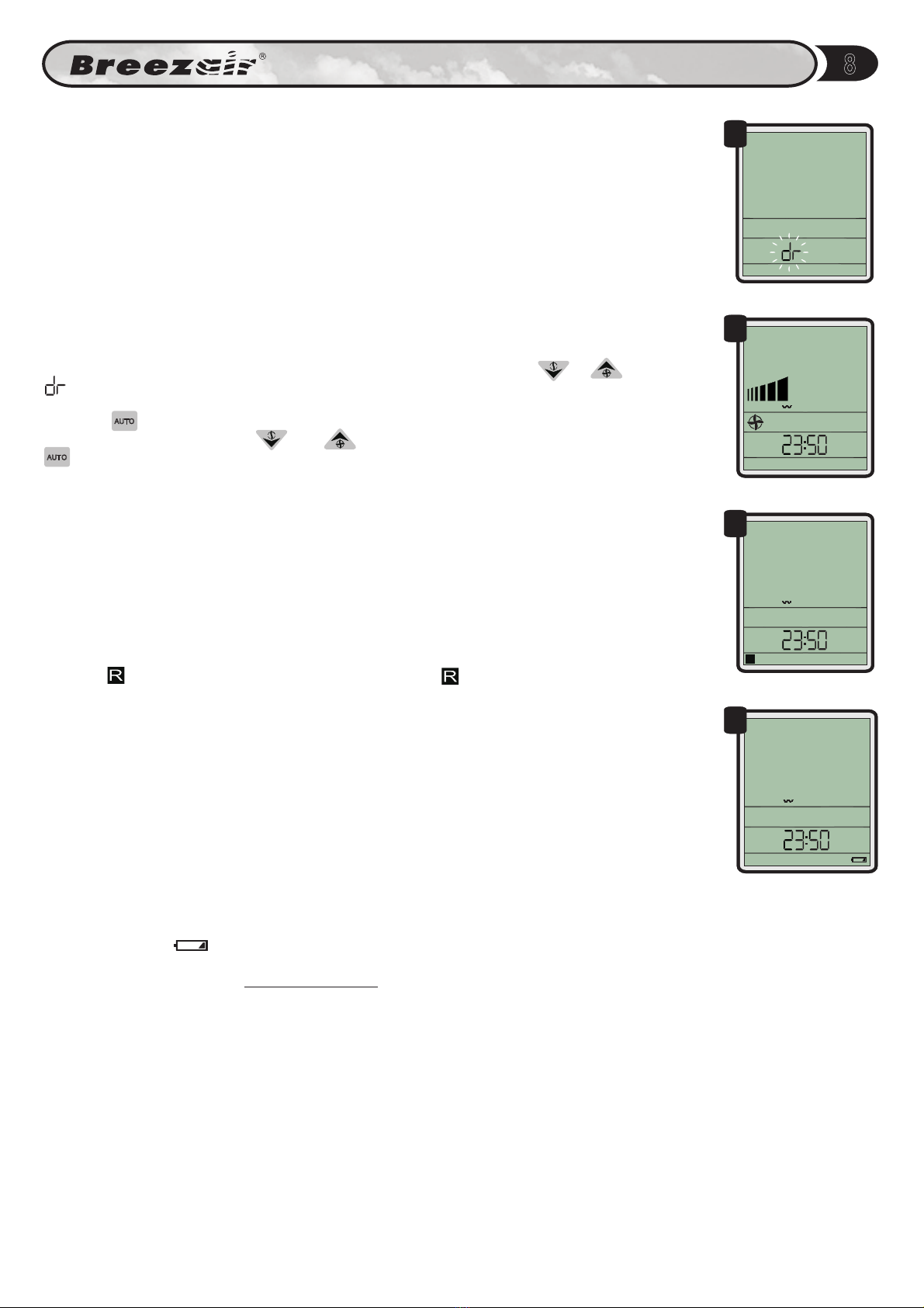
To set a delayed drain mode, enter the PROGRAM mode and press the or button until
flashes on the clock display (Fig 26).
Press the button to confirm.The current time delay will flash as four digits on the clock.
Adjust the time delay using the and buttons up to a maximum of ten minutes. Press the
button to lock the time delay and return the cooler to the OFF mode. Disconnect and
reconnect the power for this change to take effect.
AUTO
AUTO
18
Programming Wall Control
LOW BATTERY WARNING
The "Battery Low" message will appear on the Wall Control screen when power resumes
after a very long power OFF period in which the battery voltage has fallen below a functional
level. (Fig. 29). In this event, Then start the plant. The plant will not re-start
until the clock has been reset. It may not be necessary to change the batteries at this time.
Should the "Battery Low" message appear repeatedly after short duration power failures, then
replace the battery.
first reset the clock.
The battery:
IT IS NOT A POWER FAILURE BACK-UP
BATTERY AND IS NOT ON TRICKLE CHARGE.
The lithium battery in the Wall Control is a long life device that powers the real-time
clock only, during prolonged power "Off" periods.
Under normal conditions the battery should
have a life of about 10 years.
EXTERNAL CONTROL
Some of the functions of the Wall Control can be controlled by an external device, such as a PLC
or Building Management System. In this case will show on the display (Fig 27). In
EXTERNAL mode, all temperature and timer settings will be ignored. Humidity settings will be
ignored unless the external system enables humidity control. External systems may also control
the fan speed of the cooler. The bar chart on the Wall Control will show the equivalent speed
setting.
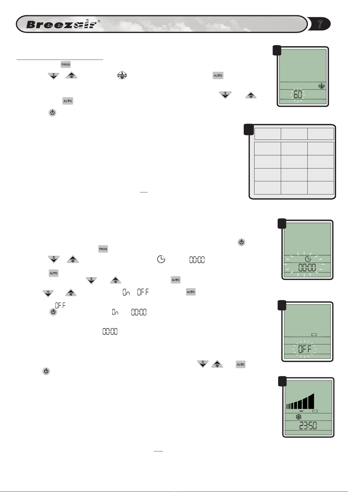
External systems may remotely switch the cooler OFF. If the cooler is in the Safety Off mode,
then, the symbol will be displayed (Fig 28). When the symbol is displayed, the IWC will
not respond to any other control input.
SAFETY OFF
EXTERNAL
R
EXTERNAL
26
27
28
29
7-DAY TIMER PROGRAM (continued)
Any day that has start and stop times set and the day switched ON will show brackets for the
day. Any day that has start and stop times set and the day switched OFF will show no brackets.
Any day that has start and stop times set to 00.00 will show no brackets.
These programs will be ignored if the cooler is in MANUAL or EXTERNAL mode during the
programmed times. This feature allows different settings for every day - start/stop, temperature &
humidity.
REMOTE ON/OFF
This input is used to turn the cooling system ON or OFF from a remote location.
The input must be in the form of a momentary pulse (provided by the installer) for both ON and
OFF functions. Any repeated pulses received within 2 seconds of the first pulse will be ignored.
When a pulse is received during cooling system operation (whether AUTO or MANUAL) the
control will save the current state of the system and the system will enter a stand-by state and
shut down.
When the next pulse is received at Input 8, the cooling system will start up again in the same
mode in which it was last shut down.
In the event that the cooling system is re-started manually during the standby state, the next
pulse received at input 8 will shut down the system into standby mode.