Brinly SA-401BH Manuale utente

1
1020084-A
Call Customer Service, Toll-Free: 877-728-8224
Important: This manual contains information for the safety
of persons and property. Read it carefully before
assembly and operation of the equipment!
Visit us on the web!
www.brinly.com
OWNER'S MANUAL
• Assembly
• Installation
• Operation
• Repair Parts
40” LAWN AERATOR
MODEL:
SA-401BH
SA-401BH-A
Scan this QR
code for additional
info on our website.
2
1020084-A
2
==================================================================================================
English Manual
INTRODUCTION AND SAFETY
CONGRATULATIONS on the purchase of your new Brinly-Hardy Aerator! Your Aerator has been designed, engineered
and manufactured to give you the best possible dependability and performance.
Should you experience any problem you cannot easily remedy, please do not hesitate to contact our knowledgeable
customer service department toll-free at 1-877-728-8224. We have competent, well trained technicians to help you with
the assembly and use of your product.
CUSTOMER RESPONSIBILITIES
- Please read & retain this manual. The instructions will enable to assemble and maintain your product properly.
- Please carefully read and observe the SAFETY SECTION of this manual.
- Follow a regular schedule in maintaining and caring for your Brinly-Hardy product.
TABLE OF CONTENTS
SAFETY ................... 2-3
PARTS .................... 4-5
ASSEMBLY . . . . . . . . . . . . . . . . 6-10
USE AND CARE
Specifications ............... 11
Installation / Removal ......... 11
Storage ...................12
Use and Maintenance ...... 12-13
Service ....................13
WARRANTY .................14
REQUIRED TOOLS
FOR ASSEMBLY
• Flat Head Screwdriver
• 1/2” Wrench
• Set of Pliers or Hammer
• Safety Glasses
• Gloves
SAFETY
This symbol will help to point out
important safety precautions throughout this
manual. It means: ATTENTION! BECOME
ALERT! YOUR SAFETY IS INVOLVED.
The machine safety labels shown in this section are placed in
important areas on your machine to draw attention to potential
safety hazards.
On your machine safety labels, the words DANGER, WARNING,
and CAUTION are used with this safety-alert symbol. DANGER
identifies the most serious hazards.
The operator’s manual also explains any potential safety
hazards whenever necessary in special safety messages that
are identified with the word, CAUTION, and the safety-alert
symbol.
RECORD PURCHASE INFORMATION
Record your purchase information in
the spaces provided below:
Date of Purchase ______________________________________
Company Name ______________________________________
Company Phone ______________________________________
Serial Number ______________________________________

3
1020084-A
3
==================================================================================================
English Manual
SAFETY
- Use this attachment for intended purpose only.
- Before you operate any feature of this attachment or towing
vehicle, observe your surroundings and look for bystanders.
- This attachment is intended for use in lawn care and home
applications. Do not tow behind a vehicle on a highway or
in any high speed applications. Do not tow at speeds higher
than the maximum recommended towing speed.
- Towing speed should always be slow enough to maintain
control. Travel slowly over rough terrain. Avoid holes, rocks
and roots. Slow down before turning.
- Do not exceed the maximum towing capacity of your towing
vehicle.
- Do not tow this product behind a motor vehicle such as a
car, truck or ATV.
- Towing this product behind a ZTR (Zero Turn Radius) mower
can affect the stability of the mower and is not recommended.
- Additionally, towing this product behind a ZTR mower is not
recommended due to the speed and sharp turning ability the
ZTR. Damage to this product or ZTR may result.
- Know your towing vehicle controls and how to stop safely,
READ YOUR OWNER’S MANUAL before operating.
- Check the towing vehicle brake action before you operate.
Adjust or service brakes as necessary.
- Do not allow children to operate the towing vehicle. Do not
allow adults to operate the towing vehicle without proper
instruction or without having read the owner’s manual.
- Always wear substantial footwear. Do not wear loose tting
clothing that can get caught in moving parts.
- Keep your eyes and mind on your towing vehicle, attachment
and area being covered. Do not let other interests distract
you.
- Stay alert for holes and other hidden hazards in the terrain.
- The towing vehicle and attachment should be stopped and
inspected for damage after striking a foreign object. Any
damage should be repaired before restarting and operating
the equipment.
- Do not drive close to creeks, ditches and public highways.
- Watch out for traf c when crossing near roadways.
- Keep the towing vehicle and attachment in good operating
condition and keep safety devices in place.
- Keep all parts in good condition and properly installed. Fix
damaged parts immediately. Replace worn or broken parts.
Replace all worn or damaged safety and instruction decals.
Keep all nuts, bolts and screws tight.
- Do not modify the attachment or safety devices. Unauthorized
modi cations to the towing vehicle or attachment may impair
its function or safety, and it will void the warranty.
GENERAL NOTES (Operation)
- Read the safety operating precautions in your towing vehicle
operator’s manual for additional safety information.
- Stopping distance increases with speed and weight of towed
load. Travel slowly and allow extra time and distance to
stop. Total towed weight must not exceed limits speci ed in
towing vehicle operator’s manual.
- Excessive towed load can cause loss of traction and loss of
control on slopes.
- Reduce towed weight when operating on slopes.
- Use only approved hitches. Tow this attachment only with a
towing vehicle that has a hitch designed for towing. Do not
connect this attachment except at the approved hitch point.
- Follow the towing vehicle manufacturer’s recommendations
for weight limits for towed equipment and towing on slopes.
Use counterweights or wheel weights as described in the
towing vehicle operator’s manual.
- Slow down before you turn and do not turn sharply. Use
additional caution when turning or operating under adverse
surface conditions.
- When reversing, carefully back-up straight to avoid jack-kni
ng. Do not allow the towing vehicle’s wheels to contact the
attachment drawbar. Damage could result.
- Do not shift to neutral and coast downhill.
TOWING VEHICLE AND TOWING SAFELY
- Keep children, bystanders and pets at a safe distance away
while operating this or any attachment.
- Use care when reversing. Before you back up, look carefully
behind for bystanders.
- Before you operate any feature of this attachment or towing
vehicle, observe your surroundings and look for bystanders.
PROTECT THOSE AROUND YOU
- Do not carry passengers.
- Do not let anyone, especially children, ride in/on this attach-
ment, the towing vehicle or hitch bracket. Riders are subject
to injury such as being struck by foreign object and/or being
thrown off during sudden starts, stops and turns.
- Riders may also obstruct the operator’s view resulting in this
attachment being operated in an unsafe manner
KEEP RIDERS OFF TOWED
ATTACHMENT AND TOWING VEHICLE

4
1020084-A
4
==================================================================================================
English Manual
HARDWARE IDENTIFIER
DO NOT RETURN PRODUCT IF YOU ARE MISSING PARTS.
Please Call: 1 (877) 728-8224
Illustrations on this page
are to scale for faster
identication of hardware
during assembly.
Hitch Pin; Drawbar, 1/2" x 2 1/2" (x1) . . . . . . . . . . . .
B-3861
13
9
Nut; Hex
5/16”-18
(x10)
30M1000P
11
Washer;
Flat, 5/16”
(x6)
45M1111P
10
Washer;
Lock, 5/16”
(x10)
40M1000P
12
Washer;
Flat, 5/8”
(x8)
45M2121P
Exterior
circumferences
of washers
can vary.
These dimensions
are a measurement
of the internal
diameter of the
washer.
Hairpin Cotter, 1/8” (x3) . . . . . . . . . . . . . . . . . . . . . . . . . .
D-146P
15
14 Square Bearing (x2) . . . . . . . . . . . . . . . . . . . . . . . . . . . . . . . . . .
B-6270
Screw: Round Head, 5/16 x 1” (x4) . . . . . . . . . . . . . . . . . . . . . . . . . . . . . . . .
20M1016P
8
Screw: Round Head, 5/16”-18 x 3/4” (x6) . . . . . . . . . . . . . . . . . . . . . . . . . . . . . .
20M1012P
7

5
1020084-A
5
==================================================================================================
English Manual
PARTS
STOP
Installation Questions? Missing Parts? Replacement Parts?
DON’T GO BACK TO THE STORE!
Please call our Customer Service Department, Toll Free: 877-728-8224 or customerservice@brinly.com
Detail 1
Detail 2
x10
6
6
x6
11
10
98
4
7
7
14
1
12
15
15
12 9
16
2
14
9
310
10
15
12
1
See Detail 1
See Detail 1
See
Detail 2
8
13
9
15
9
10
10
5
720M1012P Screw; Round Head
5/16”-18 x 3/4”
6
820M1016P Screw; Round Head
5/16” x 1”
4
930M1000P Nut; Hex, 5/16"-18 10
10 40M1000P Washer; Lock, 5/16" 10
11 45M1111P Washer; Flat, 5/16” 6
12 45M2121P Washer; Flat, 5/8” 8
13 B-3861 Pin; Hitch, 1/2" x 2-1/2" 1
14 B-6270 Bearing; Square 2
15 D-146P Cotter; Hairpin, 1/8", #211 3
16 R-821-10 DrawBar, Clevis 1
Hardware Bag 11020063
PART #s (vary by model)
Ref. Description Qty. SA-401BH SA-401BH-A
1End Panel 2 1008490-10 1008490-10
2 Tine Shaft 1 1019939 1019939
3 Drawbar, w/ Decals 1 B-3593-1 1020062 **
4 Tray, w/ Decals 1 1008589 1020080
5 Tine 10 1018833-SER *1018833-SER *
6 Bearing 20 B-5425 B-5425
*Tines come in a multi-pack (1019235).
An extra tine may be included.
** The SA-401BH-A drawbar (3) has a slightly
different appearance, illustrated here:

6
1020084-A
6
==================================================================================================
English Manual
x4
ASSEMBLY
Assembly Tip
Illustrations on page 4 are to-scale.
For faster identication of hardware during assembly,
simply lay the hardware on top of the illustration.
Additional info and videos
are available on our website:
brinly.com
This QR code links directly
to the product page.
41020084-A
4
==================================================================================================
English Manual
HARDWARE IDENTIFIER
DO NOT RETURN PRODUCT IF YOU ARE MISSING PARTS.
Please Call: 1 (877) 728-8224
Illustrations on this page
are to scale for faster
identication of hardware
during assembly.
Hitch Pin; Drawbar, 1/2" x 2 1/2" (x1) . . . . . . . . . . . .
B-3861
13
9
Nut; Hex
5/16”-18
(x10)
30M1000P
11
Washer;
Flat, 5/16”
(x6)
45 M1111P
10
Washer;
Lock, 5/16”
(x10)
40M1000P
12
Washer;
Flat, 5/8”
(x8)
45M2121P
Exterior
circumferences
of washers
can vary.
These dimensions
are a measurement
of the internal
diameter of the
washer.
Hairpin Cotter, 1/8” (x3) . . . . . . . . . . . . . . . . . . . . . . . . . .
D-146P
15
14 Square Bearing (x2) . . . . . . . . . . . . . . . . . . . . . . . . . . . . . . . . . .
B-6270
Screw: Round Head, 5/16 x 1” (x4) . . . . . . . . . . . . . . . . . . . . . . . . . . . . . . . .
20M1016P
8
Screw: Round Head, 5/16”-18 x 3/4” (x6) . . . . . . . . . . . . . . . . . . . . . . . . . . . . . .
20M1012P
7
Steps 1 & 2
1. Align the drawbar (3)
with the tray (4) using the
following, as illustrated:
- x2 5/16” x 1” Round Head Screws (8)
- x2 5/16” Lock Washers (10)
- x2 5/16” Hex Nuts (9)
2. At the end of the drawbar (3),
attach the clevis (16) using:
- x2 5/16” x 1” Round Head Screws (8)
- x2 5/16” Lock Washers (10)
- 2x 5/16” Hex Nuts (9)
NOTE: Be sure to align the
Clevis (16) in the direction shown.
9
8
8
3
4
8
9
3
16
88
8
8
9
10

7
1020084-A
7
==================================================================================================
English Manual
Steps 4 & 5
4. Fasten a Hairpin Cotter (15) on the tine shaft (2) and
add a 5/8” Flat Washer (12) on the shaft
As illustrated, push the tine shaft (2) through
one end panel (1).
5. Now add a square bearing (14) and then a 5/8” Flat
Washer (12) to the Tine Shaft.
ASSEMBLY
x6
Step 3
10
11
9
7
1
5
3. Install the two end panels (1) on each
end of the tray (5) using:
- x6 5/16” x 3/4” Round Head Screws (7)
- x6 5/16” Flat Washers (11)
- x6 5/16” Lock Washers (10)
- x6 5/16” Hex Nuts (9)
NOTE: Leave nuts loose in this step so that
the End Panels (1) can be adjusted later.
11
7
9
10
15
12
14 12
1
2
2

8
1020084-A
8
==================================================================================================
English Manual
x10
ASSEMBLY
CAUTION: GLOVES ARE REQUIRED WHEN HANDLING AERATOR TINES.
Tines have extremely sharp points. Use caution when handling.
Steps 6 & 7
Bearing (6), small end rst
Tine (5)
Bearing (6), large end rst 6
6
5
NOTE: The Bearings (6) have two small openings
and extensions. These are designed to sandwich the
Tines (5), sliding through and connecting.
5
1
12 14
66
2
6. Position the
10 tines (5) and
20 bearings (6)
on the tine shaft (2)
in the following
order:
- Bearing (6)
(small end rst)
- Tine (5)
- Bearing (6)
(large end rst)
7. Add a 5/8” at washer (12) and then a square
bearing (14) onto the Tine Shaft between the last
bearing and the end panel. Push the square bearing
into the hole on the end plate (1) as illustrated here.

9
1020084-A
9
==================================================================================================
English Manual
ASSEMBLY
CAUTION: GLOVES ARE REQUIRED WHEN HANDLING AERATOR TINES.
Tines have extremely sharp points. Use caution when handling.
Steps 8 & 9
8. Push the End Panels (1)
toward the Tines (5) until
there is no free play along
the Tine Shaft and tighten
the nuts (A) on the End
Panels. (6 nuts total).
NOTE: The Square Bearings
must be completely inserted
into the End Panels before
you tighten the nuts.
9. Push the end of the tine shaft with
the fastened hairpin cotter all the
way towards the End Panel.
NOTE: Store any extra Flat Washers in a
safe location. You may need them for
maintenance of End Panel Adjustment.
A
A
1
1
15
12
2
Next, add as many 5/8” at
washers (12) to the opposite end
of the shaft. Add as necessary to
eliminate extra space.
Fasten the remaining Hairpin Cotter (15)
on the end of the Tine Shaft (2).
10
1020084-A
10
==================================================================================================
English Manual
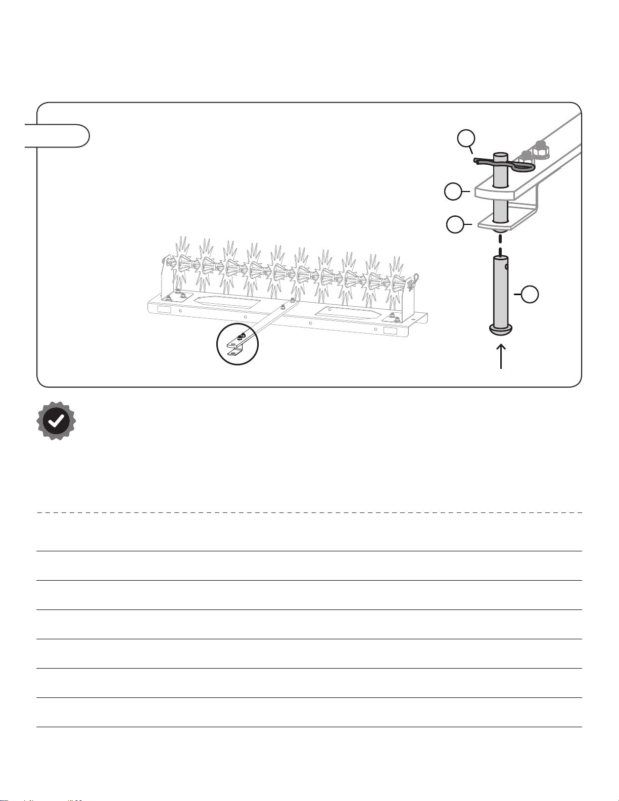
ASSEMBLY
Step 10
10. From below, install a hitch pin (13) through the clevis (16)
and tow bar (3), as illustrated.
Secure with the last hairpin cotter (15).
Assembly is Complete!
3
16
13
15
NOTES
Questo manuale è adatto per i seguenti modelli
1
Indice
Altri manuali Brinly Timone

Brinly
Brinly SATY-40 BH Manuale utente

Brinly
Brinly SAT-40 BH Manuale utente

Brinly
Brinly PA-40 BH Manuale utente

Brinly
Brinly SA-400BH Manuale utente

Brinly
Brinly SAT-40 BH Manuale utente

Brinly
Brinly PA-40 BH Manuale utente

Brinly
Brinly SA-400BH Manuale utente

Brinly
Brinly DD-550 Istruzioni per l'installazione e il funzionamento

Brinly
Brinly CC-560 Manuale utente

Brinly
Brinly SA2-40BH1-G Manuale utente


