Smart Relay 4 G2 Installation and Operation Manual
INSTALLATION
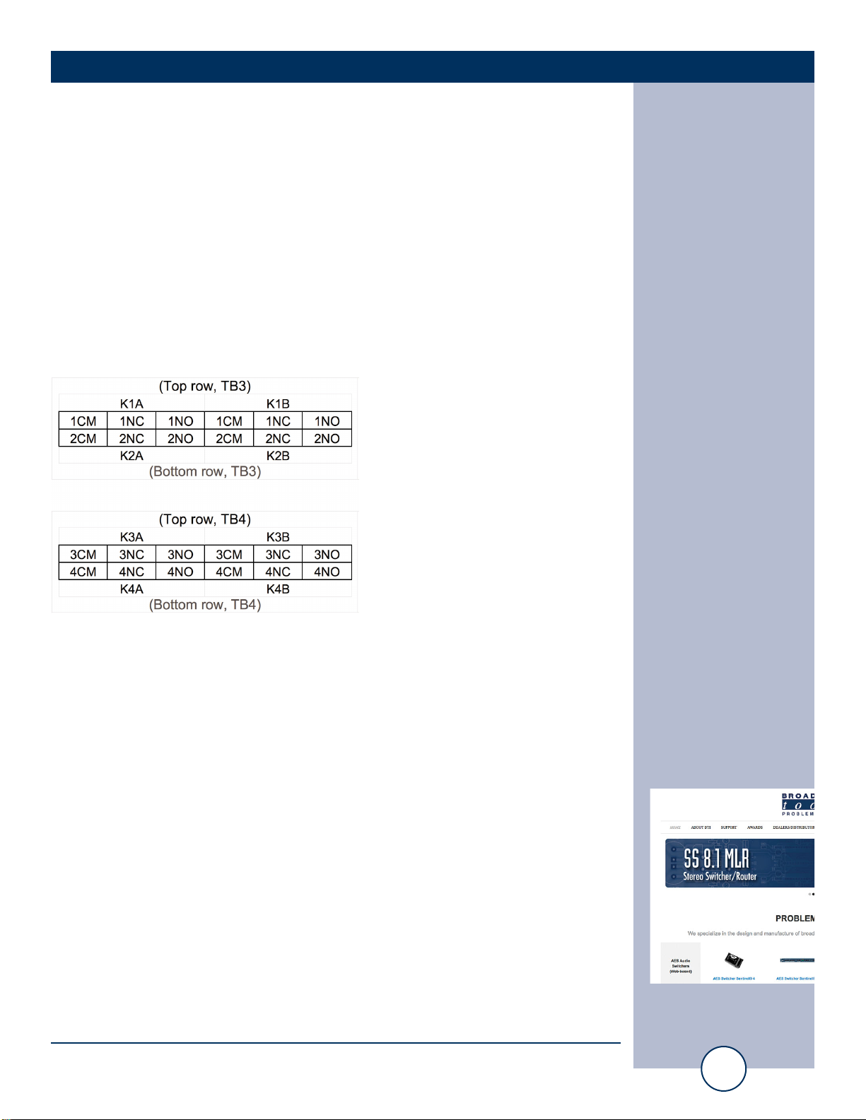
Inputs
Each optically isolated input has a terminal labelled “xA” and a terminal labelled
“xB”. Inputs can be configured for either wet or dry operation via internal jumpers.
The factory default configuration is dry, where the “A” side of the input is ground
(GND) and the “B” side of the input is the cathode (-) of the opto-isolator. In this
configuration 5V is applied internally to the anode (+) of the opto-isolator. This con-
figuration is best for interfacing with external dry contact relay outputs, switches,
and open collector outputs.
In the “wet” configuration an external voltage must be applied to the input to acti-
vate the opto-isolator. When configured for wet operation the “A” side of the input
is the anode (+) and the “B” side of the input is the cathode (-). This configuration
is best where full isolation is preferred or when interfacing with external
voltage/logic level outputs.
Each optically isolated input is connected through an internal 2.2k ohm series cur-
rent-limiting resistor directly to an opto-coupler circuit so no external resistor is nec-
essary if the input voltage is between 5 and 24 VDC. Higher DC voltages, from 25
to 48 VDC, can be used but must be reduced with an additional external resistor of
the appropriate value and power rating to limit the input current.
Here is how to calculate the value and power rating of an external current limiting resis-
tor for DC voltages up to 48 VDC: Each opto-isolated input has an internal 2.2K ohm
series resistor. The opto-isolator works well with an input current of 9 mA and has a
voltage drop of around 1.2V. With this information we can determine the correct exter-
nal series current limiting resistor value needed for other voltages using the equation:
R = ((Vin-1.2)/0.009)-2200
Where:
R = External resistor value required
Vin = Desired input voltage
1.2 V = Forward voltage drop of the LED in the opto-isolator
0.009 A = Nominal LED current
2200 ohms = Internal resistor
For example:
To connect a 48 VDC signal voltage to an input on the Smart Relay 4 G2 in “wet”
configuration the completed equation for the external resistor value would be:
R = ((48-1.2)/0.009)-2200 = 3000 ohms
To calculate the power dissipated by the external resistor, the equation would be:
P = I x I x R, so the resistor must be at least .009 x .009 x 2200 = 0.243 Watts,
use a 1/2 Watt rated resistor.
WEBSITE:
Visit our web site for
product updates and
additional information.