
Bruker BLAH500 E Manuale di istruzioni e di sicurezza
NMR Spectroscopy
Bruker BioSpin
think
forward
Version
BLAH500 E
Amplifier 700900MHz INR
Operating & Service Manual
002

The information in this manual may be altered without notice.
BRUKER BIOSPIN accepts no responsibility for actions taken as a result of use of
this manual. BRUKER BIOSPIN accepts no liability for any mistakes contained in
the manual, leading to coincidental damage, whether during installation or
operation of the instrument. Unauthorised reproduction of manual contents,
without written permission from the publishers, or translation into an other
language, either the entire manual or a part of it, is forbidden.
This manual describes the units as they are at the date of printing. On request, the
manufacturer shall supply circuit diagrams, lists of components, descriptions,
calibrating instructions and any other information for use by qualified personnel of
the user, in charge of repairing the parts of the unit which have been stated by the
manufacturer to be "repairable". Such supply shall in no event constitute
permission to modify or repair the units or approval of the same.
All rights reserved for the units, circuits, processes and appellations mentioned
herein.
This unit is not designed for any type of use which is not specifically described in
this manual. Such use may be hazardous.
For further technical assistance on the BLAH500 E unit, please
do not hesitate to contact your nearest BRUKER dealer or
contact us directly at:
BRUKER BioSpin
34 rue de l’Industrie
F-67166 Wissembourg Cedex
France
Phone: + 33 388 066 000
Fax: + 33 388 736 820
Email: support-rmn@bruker.fr
Internet: www.bruker.com
This manual was written by
This manual was edited and desktop published by
© September 24, 2009: Bruker BioSpin
Wissembourg, France
Bernard Geissert
Dominique Wurtz
P/N: Z31838
DWG-Nr: Z4D10552A

Operating & Service Manual Version 002 BRUKER BIOSPIN 3 (51)
Contents
Contents ............................................................................ 3
1 General Information ........................................................... 5
1.1 Introduction ........................................................................................ 5
2 Safety .................................................................................. 7
2.1 Identification Labels ............................................................................ 7
Identifying Plate ............................................................................. 7
Manufacturer’s Name Plate ............................................................ 8
2.2 Safety Labels and Symbols ................................................................. 9
Warning Signs ............................................................................... 9
Danger ...................................................................................... 9
Instruction ................................................................................. 9
3 Installation .........................................................................11
3.1 Initial Inspection ............................................................................... 11
Mechanical Check ........................................................................ 11
Claim for Damage ........................................................................ 11
Reshipment and Repackaging Requirements ............................... 11
Environment Requirements .......................................................... 12
3.2 Installation Requirements ................................................................. 12
Bench Operation .......................................................................... 12
3.3 Power Requirements ........................................................................ 12
3.4 System Check .................................................................................. 12
3.5 Initial Turn on Procedure .................................................................. 13
4 Operation .......................................................................... 15
4.1 Front Panel Description .................................................................... 15
Indicators ..................................................................................... 15
Coaxial Connectors ...................................................................... 16
Ethernet 10/100 Interface Connector ............................................ 16
Device Front View ........................................................................ 17
4.2 Rear Panel Description ..................................................................... 18
Device Rear View ........................................................................ 18
5 Technical Description ...................................................... 19
5.1 System Overview .............................................................................. 19
5.2 Theory of Operation .......................................................................... 23
RF Path ....................................................................................... 23
Embedded Router ................................................................... 23
RF Driver ................................................................................ 23
RF Relay H500/H50 Selection ................................................. 24

4 (51) BRUKER BIOSPIN Operating & Service Manual Version 002
Contents
RF Coupler H50 ...................................................................... 24
RF Power Amplifier ................................................................. 24
RF Coupler H500 .................................................................... 24
Circulator ................................................................................ 24
BLA Control Board ....................................................................... 25
BLA Extension Board ................................................................... 27
Status Led Board ......................................................................... 27
BIS Board .................................................................................... 27
6 Servicing the BLA .............................................................29
6.1 Accessing the BLA Amplifier ............................................................. 29
6.2 Sub Toolbar Information ................................................................... 30
Device Information (default) ......................................................... 30
Amplifier Status ........................................................................... 31
6.3 Sub Toolbar Advanced Operations ................................................... 32
Device Information (advanced) .................................................... 32
Amplifier Limitations .................................................................... 33
Change Limits ............................................................................. 34
Routing Information and Setting ................................................... 35
6.4 Sub Toolbar Maintenance ................................................................. 36
Device Information (maintenance) ............................................... 36
Self-Test & Software Reset .......................................................... 37
Firmware Update ......................................................................... 39
BIS Content ................................................................................. 40
7 Specifications ...................................................................41
7.1 Common Characteristics .................................................................. 41
7.2 General Specifications ..................................................................... 42
Channel High Resolution 50W Output .......................................... 42
Channel Solid 500W Output ......................................................... 43
8 Service Information and Maintenance ..............................45
8.1 Preventive Maintenance of the RF Module on BLA-Type Amplifiers .. 45
Operation .................................................................................... 45
Figures ............................................................................. 47
Tables ............................................................................... 49

Operating & Service Manual Version 002 BRUKER BIOSPIN 5 (51)
1
General
Information 1
Introduction 1.1
The BLAH500 E Amplifier 700-900MHz INR is a broadband linear pulse power
amplifier specifically designed for Nuclear Magnetic Resonance (NMR)
application for 16,4 to 21,1 Teslas Systems. It is commercialized under the
BRUKER BIOSPIN part number W1345505.
It is operated in AB linear class and provides 500W and more peak RF power over
the frequency range 650-900MHz on the H500 output for the Solid applications
and 50W and more peak RF power on the H50 output for the High Resolution
applications.
The amplifier is equipped with N-Channel RF LDMOSFETs transistors of the
latest generation. The unit can provide full power for any combination of pulse
width and duty cycle up to 100ms and 20% in High Resolution mode and 10% in
Solid mode.
Its built-in protection circuitry will allow lower power pulses for longer pulse widths
and duty-cycles, maintaining a 50W average power for the Solid application on
the H500 output and 10W average power for the High Resolution application on
the H50 output.
The electronic protection circuitry has been designed to protect against:
•Excessive power output level (overdrive)
•Excessive pulse repetition rate (over duty-cycle protection)
•Excessive pulse duration (over pulse-width)
•More than 50% reflected RF power (mismatch when VSWR ≥6)
•Thermal protection (overheat)
The amplifier is powered by an internal switched power supply assembly that
provides the +32VDC for the power amplifiers, in addition to all low level voltages
for the system.
The supply is self protected for overcurrent and overvoltage.
The entire unit is housed in a 19", 3U, 520mm rack cabinet.

6 (51) BRUKER BIOSPIN Operating & Service Manual Version 002
General Information
Operating & Service Manual Version 002 BRUKER BIOSPIN 7 (51)
2
Safety 2
The BLAH500 E Amplifier 700-900MHz is in accordance with the standard
61010-1 and with the UL 61010-1 / CSA C22.2 No.61010-1-04 Safety
Requirements for Electrical Equipments.
Identification Labels 2.1
Labels are provided to alert operating and service personnel to conditions that
may cause personal injury or damage to the equipment from misuse or abuse.
Please read the labels and understand their meaning.
Identifying Plate 2.1.1
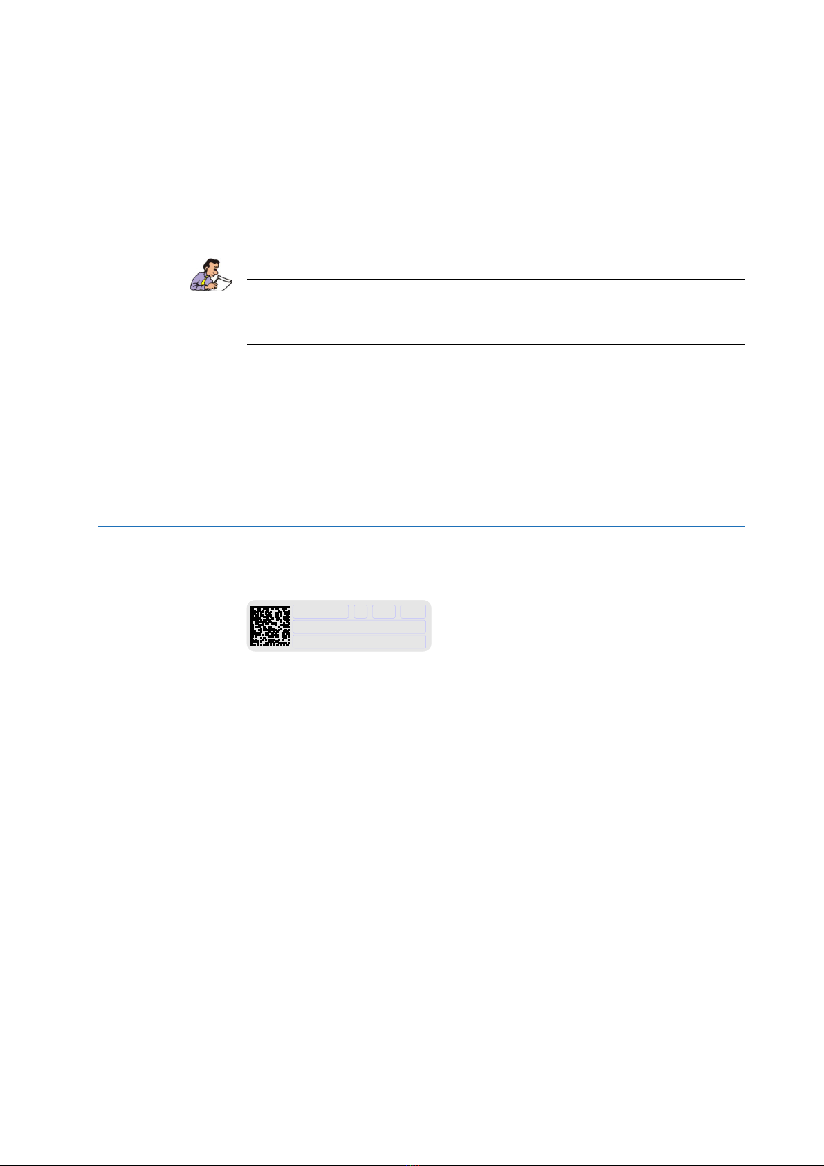
The BLAH500 E Amplifier 700-900MHz can be identified by an identifying plate at
the front panel of the unit that contains the following information :
Figure 2.1. Identifying Plate
•(A) Part Number
This field indicates the part number of the product.
•(B) Variant
This field indicates the variant number that identifies the production category of
the product. The default variant is 00.
•(C) ECL
This field indicates the revision number that identifies the product
configuration. The initial revision is 0.00.
•(D) Serial Number
This field indicates the serial number of the product.
•(E) Type
This field contains the designation of the product.
•(F) Information
This field contains additional information about the product.
A///BC D
E
F

8 (51) BRUKER BIOSPIN Operating & Service Manual Version 002
Safety
Manufacturer’s Name Plate 2.1.2
The BLAH500 E Amplifier 700-900MHz can be identified by a manufacturer’s
name plate at the back panel of the unit that contains the following information :
Figure 2.2. Manufacturer’s Name Plate
•(A) Voltage
This field indicates the input mains voltage of the product.
•(B) Frequency
This field indicates the input mains frequency of the product.
•(C) Phases
This field indicates the number of phases of the mains.
•(D) Power
This field indicates the absorbed power of the product.
•(E) Current
This field indicates the absorbed current of the product.
•(F) Wires
This field indicates number of wires with the ground in the mains cord.
•(G) Part Number
This field indicates the assembly number that identifies the part number of the
product.
Hz
Made in France
VAC
Wires +
A B C Phase
FD KVA Gnd
EAmps
P/N : G

Operating & Service Manual Version 002 BRUKER BIOSPIN 9 (51)
Safety Labels and Symbols
Safety Labels and Symbols 2.2
Warning Signs 2.2.1
Danger
Instruction
Operating personal should not remove RF output cable without turn off the power
supply because the RF output can cause serious burns before the "Mismatch"
protection is active.
Please disconnect the mains supply before opening to prevent potential hazard
such as :
•Electrical shock from power supply
•Contact burns from the RF module and heatsink
•Finger scratch due to the fan assembly on the RF module.
DANGER! Risk of electrical shocks
Throughout this manual, this symbol indicates the possibility of
severe personal injury, loss of life or equipment damage if the
instructions are not followed.
On the equipment, the symbol also implies a danger and alerts the
user.

10 (51) BRUKER BIOSPIN Operating & Service Manual Version 002
Safety
Indice
Altri manuali Bruker Amplificatore


