Calomax Clipper2 Manuale utente

Clipper2
INSTALLATION, OPERATION AND MAINTENANCE
MANUAL
Patented Wall-mounted Catering Water Boiler
Read these instructions thoroughly before
commencing installation or undertaking
maintenance work. Issue 17 –DCR 668: 9/5/05
TEL: 0113 249 6681 FAX: 0113 235 0358 www.calomax.co.uk

Issue 17 page 1
Issue 17 page 1
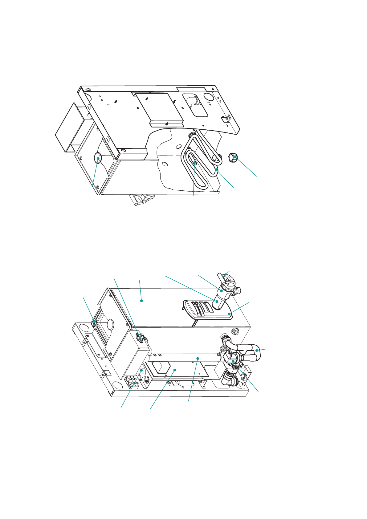
NBPRG Pressure
relief grommet
NBE3HK
3kw element
TAK
Thermistor
assembly kit
15BC Drain plug
requires 15BCW
Washer
(Body and Backplate cut away to show internal components)
NBWPT
Water pipe
GTT Tap top
assembly
UTB
Draw off tap body
5PMFK
Plastic moulded fascia
houses light PCB
COMLPCBA
NB5B Body
NB5BLG Body
lid gasket
NBSV
solenoid
valve
CASPCBT
Printed circuit
board (includes
Triac PCB)for
single thermistor
units only
NB5WLCPT
Water level
control pipe
NBMR Manual
reset
Note
For the Outer Casing order NB5OCWSS
(Stainless Steel) or NB5OCWMS (White)
For an Insulation set order NB5IS
Vent and
overflow pipe
with screen
UTHSG
Heat Shroud
If parts required are not
identified, please contact
Calomax ltd
PARTS IDENTIFICATION FOR CLIPPER 5L

Issue 17 page 2
Issue 17 page 2
If parts required are not
identified, please contact
Calomax ltd
NBPRG Pressure
relief grommet
NBE3HK
3kw element
TAK
Thermistor
assembly kit
15BC Drain plug
requires 15BCW
Washer
(Body and Backplate cut away to shown internal components)
GTT Tap top
assembly
UTB
Draw off tap body
7.5PMFK Plastic
moulded fascia (houses
light PCB:COMLPCBA)
NB10B Body
NB10BLG Body
lid gasket
NBSV
solenoid
valve
CASPCBT
Printed circuit
board (includes
Triac PCB) For
single thermistor
machines only
NB7.5WLCPT
Water level
control pipe
NBMR Manual
reset
Note
For the Outer Casing order NB10 OCWSS
(Stainless Steel) or NB10 OCWMS (White)
For an Insulation set order NB10IS
Vent and
overflow pipe
UTHSG
Heat Shroud
NBWPT
water pipe
PARTS IDENTIFICATION FOR CLIPPER 7. 5L

Issue 17 page 3
Issue 17 page 3
NBPRG Pressure
relief grommet
NBE3HK
3kw element
TAK
Thermistor
assembly kit
15BC Drain plug
requires 15BCW
Washer
(Body and Backplate cut away to show internal components)
If parts required are notidentified, please contact
Calomax ltd
NBPRG Pressure
relief grommet
NBE3HK
3kw element
TAK
Thermistor
assembly kit
15BC Drain plug
requires 15BCW
Washer
(Body and Backplate cut away to show internal components)
GTT Tap top
assembly
UTB
Draw off tap body
10PMFK
Plastic moulded fascia
(houses light PCB:
COMLPCBA)
NB10B Body
NB10BLG Body
lid gasket
NBSV
solenoid
valve
CASPCBT
Printed circuit
board (includes
Triac PCB)For
sungle themistor
units only
NB10WLCPT
Water level
control pipe
NBMR Manual
reset
Note
For the Outer Casing order NB10 OCWSS
(Stainless Steel) or NB10 OCWMS (White)
For an Insulation set order NB10IS
Vent and
overflow pipe
NBWPT
water pipe
UTHS
heat
shield
PARTS IDENTIFICATION FOR CLIPPER 10L

Issue 17 page 4
Issue 17 page 4
NBPRG Pressure
relief grommet
NBE3HK
3kw element
TAK
Thermistor
assembly kit
15BC Drain plug
requires 15BCW
Washer
(Body and Backplate cut away to show internal components)
NB15B Body
NB15BLG Body
lid gasket
NBSV
solenoid
valve
CASPCBT
Printed circuit
board (includes
Triac PCB)For
single thermistor
units only
NB15WLCPT
Water level
control pipe
NBMR Manual
reset
Note
Vent and
overflow pipe
WITH SCREEN
For the outer-casing order
NB15OCWSS (Stainless steel)
or NB15OCWMS (white)
For insulation set order NB15IS
UTHSG
Heat Shroud
NBWPT
water pipe
GTT grey
tap top
UTB universal tap body
15PMFK plastic moulded
fascis (houses light
PCB:COMLPCBA)
If parts required are not
identified, please contact
Calomax ltd
PARTS IDENTIFICATION FOR CLIPPER 15L

Issue 17 page 4
Issue 17 page 4
NBPRG Pressure
relief grommet
NBE3HK
3kw element
TAK
Thermistor
assembly kit
15BC Drain plug
requires 15BCW
Washer
(Body and Backplate cut away to show internal components)
GTT tap topassembly
UTB
Draw off tap body
15PMFK
plastic moulded fascia
(houses light PCB:
COMLPCBA)
NB15B Body
NB15BLG Body
lid gasket
NBSV
solenoid
valve
CASPCBT
Printed circuit
board (includes
Triac PCB)For
single thermistor
units only
NB15WLCPT
Water level
control pipe
NBMR Manual
reset
Note
Vent and
overflow pipe
WITH SCREEN
For the outer-casing order
NB15OCWSS (Stainless steel)
or NB15OCWMS (white)
For insulation set order NB15IS
UTHSG
Heat Shroud
NBWPT
water pipe
If parts required are not
identified, please contact
Calomax ltd PARTS IDENTIFICATION FOR CLIPPER 15L

2. PLANNING THE
INSTALLATION
All installation and maintenance work must be
carried out by competent persons
2.1 Water Requirements
The unit is designed to be connected to a cold water rising
mains supply, using 15mm Table 'X' copper tube. with a
minimum pressure of 20 KPa (0.2bar) and a maximum
pressure of 1000 KPa (50bar).
to the cold water mains
supplying the boiler. It is also recommended that an
isolating valve be fitted to the mains water supply to
facilitate maintenance.
The formation of scale in hard water areas is a problem
associated with all hot water appliances. Damage to the
boiler caused by excessive scale deposits is not covered
by the manufacturer's warranty.
So as to comply with the U.K. Water Supply Regulations a
single-check valve must be fitted
2.2 Electrical Requirements
The installation must comply with the current I.E.E. Wiring
regulations, if in doubt consult a qualified electrician.
This appliance must be earthed.
The boiler complies with the Electrical Equipment Safety
Regulations (SI1994/3260) and has been independently
tested to BS EN 60335-2-63 :.
The boiler operates a nominal 3 kW element at 240V.
50Hz. supply.Acircuit diagram is provided on page 9.
2.3 Installation Location
To comply with recommendations from the health and
safety executive it is important that due consideration
be given to the safe operation of the controls of the
boiler. The boiler should therefore be mounted in such
a manner that the operator can stand directly facing
the machine with the controls at the recommended
height . Consideration should also be given
to the servicing requirements of the machine.
S
Ensure
the type of wall construction and fixings are suitable
to support the working weight of the boiler
S
ee fig. 1
ee fig.3
2.4 Vent / Overflow Pipe Requirements
The vent and overflow pipe should be extended on site
using 15mm Speed-fit plastic tube or 15mm Table 'X'
copper tube. The pipe must be laid with a ,
discharging to a safe and visible position.
continuous fall
The vent and
overflow pipe should not be connected directly to a
soil pipe and should never be allowed to become
blocked or restricted .See fig 2
The height from floor
to draw off tap handle
should be 1200mm +/-
100mm
Fig 1
Model Physical Dimensions Weights (kg)
ABC
Dry Working
5L 511 313 226 10 17
7.5L 582 368 251 13 24
10L 582 368 251 13 27
15L 623 401 274 15 35
All dimensions in mm
Fig 3
ü
û
Incorrect
Correct
ü
Correct
Vent and Overflow
Pipe-work should be fitted with a
continuous fall to a safe and visible point
of discharge (e.g. a sink). It should not be
connected directly to a waste system
because taste and smell problems will
occur.
This installation allows the silicone hose to
fit loose inside a fixed fitting. Air is allowed
into the boiler at this point and will allow
the boiler to breath in the event of the
overflow becoming trapped.
Trapped water
prevents boiler
breathing
Fig 2.
Fig 4
Vent / Overflow
Solenoid water
inlet
Cable entry clamp
Issue 17 page 5
Issue 17 page 5

3. INSTALLATION
Sufficient room must be given above, below and to the left
hand side of the boiler to allow maintenance access and
removal of the outer casing (see fig. 3).
Connect the mains water supply to the boiler solenoid
inlet , using the supplied elbow compression fitting.
1.
2.
3.
Connect the vent / overflow pipe (see fig.2) using
Speedfit plastic tubing or 15mm table 'X' copper tubing.
Connect the electrical supply to the unit via the terminal
block. The cable must be secured by the cable clamp,
(see fig. 4 ). The electrical connections to the terminal
block must be made as shown in fig.5.
The Vent/ overflow pipe and arranged
such that the outlet position is safe, visible and
external to the boiler. The overflow pipe
and should never be
allowed to become blocked or restricted .
red or brown L
black or blue N
green / yellow
must be fitted
must not be
connected directly to a soil pipe
to the terminal marked
Figure 6. shows the approximate times for boiling water to
be available at the draw off tap, from commissioning.
These times will vary depending on the water pressure of
the mains water supply.
5. USER INSTRUCTIONS
Boiling water is dispensed through the draw off tap, which
is operated by pulling the handle forward towards the user.
The tap handle will
automatically return to the off position unless pulled fully
forward to the locking position.
Two lights mounted on the front facia provide a continuous
display of the operation of the boiler. During the initial
commissioning process or subsequent switch on from
cold, the top ' ' light will indicate ' ' by
flashing yellow ( water is below normal operating
temperature). When the boiler has reached the normal
operating temperature, the ' ' light will
indicate ' ' by turning to a if the boiler is
only part full , or a light when maximum draw
off capacity is available.
If the available water is drawn from the boiler , the flow
rate will reduce to a trickle as the unit fills and heats the
water (this does not indicate a fault with the boiler). The
' ' light will continue to show ' ' as the
temperature of the water is still approximately 98 C.
Due caution should be exercised as the water is
approximately 98 C. at all times.
solid yellow
solid orange
o
o
WAIT / READY WAIT
WAIT / READY
READY
WAIT / READY READY
all
Model Approximate times for boiling water to
be available, from commissioning
5L 18 mins
7.5L 26 mins
10L 32 mins
15L 47 mins
Fig 6.
5.1 Cleaning
When required the unit should be wiped down using a
damp cleaning cloth
This appliance is not protected against the ingress of water
and therefore should not be washed down in any manner
that would allow water to enter the electrical chamber of the
unit e.g. the use of a spray water jet .
5.2 Service Indicator Light
Certain types of operational fault will cause the
'SERVICE INDICATOR light, mounted on the front
fascia to flash. If this occurs refer to section on , 'Fault
Finding' .
'
Issue 17 page 6
Issue 17 page 6
Fig 5.
4. COMMISSIONING
1. Turn on the water supply.
2. Turn on the electrical supply.
After a few seconds delay for the electronics to charge,
the boiler will begin filling with water and the 'WAIT /
READY' light will flash yellow indicating 'WAIT'. When the
low water level is reached the element will begin to heat
the water. the solenoid will remain on until the normal
operating level is reached. Upon reaching the correct
temperature the 'WAIT / READY ' light will turn solid
orange , indicating 'READYAND FULL ' .
The unit will fill and heat the water in cycles. The machine
will allow only a limited amount
On initial switch-on only
On subsequent operation of the boiler
NOTE : PRE-APRIL /02 MODELS HAD SLIGHTLY
DIFFERENT MODE OF OPERATION
of water to enter the unit
and then switch off the solenoid and switch on the
element.

Issue 17 page 7
Issue 17 page 7
6. MAINTENANCE
Competent persons must carry out all maintenance
work.
When the body lid has been removed , It is
recommended that a new body lid gasket be fitted on
re-assembly to ensure a steam tight seal. Damage to
the unit caused by incorrectly sealed gaskets that
should be replaced during maintenance is not
covered by the manufacturers warranty.
6.1 Scale
The solenoid valve is fitted with a removable filter at
the inlet point. This filter should be cleaned as
required.
Check the extent of scale formation on the element,
thermistor etc. (See parts identification drawings ).
Your Clipper 2 boiler incorporates an integral scale
inhibitor. In general, independent users throughout the
country have benefitted from either a vastly reduced
scale build up, and / or much easier maintenance due to
the softer nature of the scale which does not adhere
rigidly to the internals of the machine. Please note that
this is not a scale eliminator and its effect will differ
according to the water quality in your area.
To ensure regular, trouble-free operation, periodically
check for scale inside the boiling chamber and around the
tap nozzle. The production of scale is a natural
phenomenon and some de-scaling may be required
within the first 12 months. This is not covered under the
product’s warranty as it is not a fault.
6.2 De-scaling
NB Do not over-
tighten the drain plug when re-fitting.
Allow the contents of the boiler to cool sufficiently for the
water to be removed safely using the drain plug (see fig.
7). The body can now be de-scaled
Fig 7
Scale deposits should be removed from all internal
surfaces, particularly the heating element, thermistor
pocket etc. by gently tapping or scrapping. If the deposits
are soft, use a nylon pad and flush out. Abrasive cleaning
materials containing scouring powders and detergents
must not be used, such materials can cause taste
problems. Chemical de-scalants must only be used in
accordance with the manufacturer's instructions.
The element and thermistor can be replaced by removing
the back-nuts and washers and withdrawing from inside
the body.
IMPORTANT All chemical agents must be completely
flushed out to avoid taste problems, health risks and
possible signalling failures.
6.3 Replacing the Element and Thermistor
IMPORTANT: a new body lid gasket may be
required.
6.4 Replacing the Printed Circuit Board (PCB)
1.
2.
3.
4.
5.
6.
7.
IMPORTANT: both the main printed circuit board and
the Triac printed circuit board must be replaced as a
matched pair.
and secure it with the
single fixing screw.
Disconnect the wiring connections to the Main PCB
Remove the PCB by pulling it forward off the supports.
Disconnect the wiring connections to the Triac PCB(see
fig 8)
Remove the Triac PCB by releasing the fixing screw and
pulling it forward off the supports (see fig. 8 for location of
Triac PCB).
Apply a thin covering of heat transfer compound
(supplied) to the mounting platform of the new Triac PCB
and fit the new triac P.C.B. onto the two P.C.B. supports,
ensure it is positively located
Reconnect the Triac wiring connections, see the circuit
diagram on page9.
Position the main P.C.B. on the four supports, ensuring
that the P.C.B. is positively located.
Reconnect the P.C.B. wiring connections, see the circuit
diagram on page 9.
Triac PCB
Fig 8.

6.5 Replacing the Solenoid
2.
3.
4.
IMPORTANT: In areas where scale can be a problem ,
check that the suspected fault is not due to a blocked
filter before
replacing the unit . Scale build-up in the filter can
cause intermittent problems.
the pipe will retain a volume
of water that will be released when the connection is
broken.
(this is removable at the inlet to the solenoid)
Remove the silicone hose that joins the solenoid to
the water inlet.
Pull the solenoid from the mounting bracket.
Fit the replacement valve onto the existing mounting
bracket (if a mounting bracket was supplied with the new
valve, remove this first).
1.
NB Do not
over-tighten the drain plug when re-fitting.
Allow the contents of the boiler to cool sufficiently for
the water to be removed safely using the drain plug (see
fig. 7). The body can now be de-scaled
Warning
IMPORTANT: The correct operation of the boiler relies
on a regulated flow of water from the solenoid valve
and therefore a genuine replacement part supplied by
Calomax must be fitted.
6.6 Checking the overflow screen
Refer to the parts identification drawings on pages
1,2,3 and 4 to identify the location of the overflow
screen
.
1. Remove the P.C.B. and support bracket as one
assembly by releasing the two fixing screws.
3.
. The Overflow screen can be removed by easing
off the silicone tubing at each end. Check the screen for
blockage. The overflow screen can be cleaned or replaced
with a new part (supplied by Calomax) as required.
6.7 Adjusting the Water Temperature Set Point
The temperature potentiometer (Pot) is pre-set at
Calomax and will only require adjustment in
exceptional circumstances.
The temperature adjustment Pot 1 (located at the bottom
left hand corner of the main printed circuit board) controls
the operating temperature of the boiler. ½ turn clockwise
on this device will raise the temperature of the water by
approximately 1 ½ degrees centigrade. Water boils at
different temperatures depending on barometric
pressure. The temperature should not be tuned
higher than the pre-set 98 degrees, or overboiling
may occur during low barometric pressure
conditions, causing the unit to trip the overheat cut-
out device.
Any adjustments made to the P.C.B should
be noted on the boiler to aid fault diagnosis
if problems persist.
Issue 17 page 8
Issue 17 page 8
7. FAULT FINDING
To protect the unit in the event of continuous over
boiling, the unit is fitted with a thermal cutout device.
This device will cut power to the entire machine and
can be re-set manually. Before re-setting the device,
the cause of the trip.(de-scale required etc.) should
be investigated.
The Service Indicator Light on the front of the machine
and Light Emitting Diodes (LED’s)fitted to the Main PCB,
can be used to diagnose operating problems with the
machine.
Certain types of operational fault will cause the green
' light, mounted on the front facia,
to flash certain sequences.
SERVICE INDICATOR'
.A -light pulse generally indicates that the low
level probe requires a de-scale .
A light pulse indicates a loss of signal from the
normal water level probe causing the unit to overfill,
The probe requires a de-scale.
A -light pulse indicates the machine has over-
filled due to debris trapped in the solenoid valve. This
is usually solved by drawing water from the tap,
causing the valve to operate and flush out the
obstruction.
If this does not rectify the
problem, turn off the water supply and clean the
valve’s filter of debris.
A light pulse indicates the boiler has over filled
due to scale on both the low and normal level sensors.
A light pulse indicates
L
two
three-
four
five-
six-
The unit can be used normally while the service
indicator is flashing
all
The machine will reset itself once the
problem has cleared.
the machine has over-filled
due to debris trapped in the solenoid valve.(
) but also the low level probe requires a descale.
see four
pulse
For further information contact Calomax ltd direct.
Stating Model, S.No, and fault
symptoms.
ED’s fitted to the Main PCB indicate the operation of
the solenoid and element. The red LED indicates that
the element should be energized and the yellow LED
indicates that the solenoid should be energized.
The switching of the element and solenoid is all solid
state, driven by the PCB’s .In all cases the power to the
element and solenoid is switched through the neutral
connection.
Indice
Altri manuali Calomax Caldaia

Calomax
Calomax QUANTUM-e Guida utente

Calomax
Calomax KUDOS 6 DUAL FLOW Manuale di formazione

Calomax
Calomax CASCADE-6TC Manuale del proprietario

Calomax
Calomax eclipse 3C5 Guida utente

Calomax
Calomax Clipper 2 5L Guida utente

Calomax
Calomax QUASAR 2 Guida utente

Calomax
Calomax Quantum Manuale utente

Calomax
Calomax Quantum Manuale utente

Calomax
Calomax ECLIPSE HT3C10 Guida utente

Calomax
Calomax CB32 Guida utente