
Campbell SDM-CD16AC Manuale utente

Revision:08/2021
Copyright © 1987– 2021
Campbell Scientific, Inc.

Table of contents
1. Introduction 1
2. Control specifications 2
3. Power considerations 3
4. Installation 4
4.1 Wiring 5
4.1.1 SDM-CD16AC power and control connections 5
4.1.2 Controlled device to SDM-CD16AC connections 5
4.1.3 Motor control 6
5. Address selection switches 7
6. Data logger programming 8
6.1 CRBasic programming 9
6.1.1 SDMCD16AC() instruction 9
6.1.2 SDMSpeed() instruction 9
7. Theory of operation 10
8. Program examples 11
8.1 CRBasic examples 11
8.1.1 Controlling two SDM-CD16ACs 11
8.1.2 Control temperature and fans 11
Table of Contents - i
1. Introduction
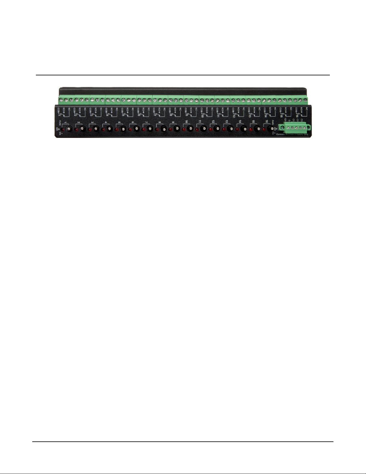
FIGURE 1-1. SDM-CD16AC face panel
The SDM-CD16AC has 16 AC/DC relay control ports (see FIGURE 1-1 (p. 1)). Each relay port can be
controlled by a data logger or controlled manually with a manual override toggle switch.
The toggle switch has three positions: ON and OFF for manual override, and AUTO for data
logger control. In the ON position, the common (COM) and normally open (NO) contacts are
closed (see FIGURE 4-1 (p. 6)). In the AUTO position, the state of the relays are controlled by the
data logger control ports.
The SDM-CD16AC is a synchronously addressed data logger peripheral. Three ports on the data
logger are used to address the SDM-CD16AC, then clock out the desired state of each of the 16
control ports. Up to 16 SDM-CD16ACs may be addressed, making it possible to control a
maximum of 256 ports from the three data logger ports.
Compatible Campbell Scientific data loggers use the CRBasic instruction SDMCD16AC() to
control the SDM-CD16AC.
SDM-CD16AC 16 Channel AC/DC Controller 1

2. Control specifications
Operating temperature: –40 to 55 °C
Operating voltage: 12 VDC nominal (11 to 18 VDC)
Current drain at 12 VDC: 6 mA quiescent; 45 mA per active LED (switch on or auto
active)
Total cable length: Cable lengths should be kept as short as possible; 6m (20ft)
(for many applications); lengths longer than 6m (20ft) may be
possible for CRBasic data loggers if the SDMSpeed()
instruction is used
Toggle switch: ON/OFF manual override; AUTO for data logger control
RELAY SPECIFICATIONS
Arrangement: Single pole double throw
Break before make
Contact material: Gold-clad silver
Individual contact rating
Normally Open rating: 5A at 30VDC, 5A at 125VAC, 5A at 250VAC
Normally Closed rating: 1A at 30VDC, 3A at 125VAC, 2A at 250VAC
Coil voltage: 11 to 18 VDC
Coil resistance: 360 Ohms ±10%
Expectedlife(contactclosures): Mechanical 107
Actuation/release time: Approx. 4 ms
Standards: Underwriters Laboratories (UL) listed product (E162021)
Canadian Underwriters Laboratories (CUL) listed product
(5Z21)
SDM-CD16AC 16 Channel AC/DC Controller 2

3. Power considerations
The SDM-CD16AC power requirements are large compared to most Campbell Scientific
products. For most applications, an external power supply (see FIGURE 3-1 (p. 3)) is
recommended to power the SDM-CD16AC.
For some applications, it may be convenient to use the data logger supply to power the
SDM-CD16AC (see FIGURE 3-1 (p. 3)). For long-term applications, the lead acid power supply
available with Campbell Scientific data loggers should be used, allowing the batteries to be float
charged. It is not recommended that the data logger alkaline supply be used to power the
SDM-CD16AC for long-term applications due to its large power requirements.
FIGURE 3-1. Connection block diagrams
SDM-CD16AC 16 Channel AC/DC Controller 3

4. Installation
lThe SDM-CD16AC must be installed in an enclosure that provides a pollution degree 2
environment (normally, only nonconductive pollution; however, a temporary conductivity
caused by condensation may be expected). All Campbell Scientific enclosures meet this
requirement.
lUse copper conductors only.
lWire Range: 30 – 14 AWG
lTightening Torque: 5 – 7 in/lb
lUse minimum 60/75 °C wire.
lInput power must be connected to a class 2 supply only. All Campbell Scientific power
supplies meet the class 2 supply requirements.
CAUTION:
Cables connecting the data logger and SDM device should be kept as short as possible to
minimize the risk of corruption of the signals and damage from induced surges. Where long
cable runs (>3m) are unavoidable and the cables run outside, some extra protection may be
required for the SDM control ports. Please contact Campbell Scientific for further advice.
When connecting wires to the SDM signal ports, please ensure they are at ground potential
before making the connection by touching them to the earth terminal.
For data logger connections, see Table 4-1 (p. 5).
Multiple SDM-CD16ACs may be wired in parallel by connecting the data logger side of one
SDM-CD16AC to the next. The CABLE5CBL-L or an equivalent cable is used to connect the
module to the data logger. A 0.3m (1ft) cable length should be sufficient when both data logger
and SDM-CD16AC are housed within an ENC12/14; a 0.6m (2ft) length may be required if the
data logger and SDM-CD16AC are housed at opposite ends of an EN16/18 enclosure.
CRBasic data loggers should use the SDMSpeed() instruction if the cable length is longer than
6m (20ft).
NOTE:
SDM cables in noisy environments need to be suitably shielded.
SDM-CD16AC 16 Channel AC/DC Controller 4

4.1 Wiring
4.1.1 SDM-CD16AC power and control connections
Refer to FIGURE 3-1 (p. 3) and Table 4-1 (p. 5) for SDM-CD16AC operating power and control
connections to the data logger.
Table 4-1: Data logger to SDM-CD16AC connections (see caution)
Connection Order SDM-CD16AC Data Logger
(see notes) Function
First 12V 12 V on data logger or
External supply Power
Second GGnd Common ground
C1 SDM-C1 (CR3000) or
C1 (other data loggers) Data
C2 SDM-C2 (CR3000) or
C2 (other data loggers) Clock
C3 SDM-C3 (CR3000) or
C3 (other data loggers) Enable
CAUTION:
The order in which connections are made is critical. Always connect 12 V first, followed by
ground, then Control Ports.
NOTE:
The CR6 allows SDM operation through terminals C1,C2, and C3 as shown in Table 4-1 (p. 5).
In addition, the Uterminals on the CR6 may be used in the same manner. U1–U3,U5–U8, and
U9–U11 are usable in the same Data,Clock,Enable order as the Cterminals.
4.1.2 Controlled device to SDM-CD16AC connections
DANGER:
ELECTROCUTION HAZARD! USE EXTREME CAUTION WHEN WORKING WITH HIGH
VOLTAGE INPUTS. DO NOT COME IN CONTACT WITH HOT LEADS!
FIGURE 4-1 (p. 6) shows how the switches in each channel operate. NO means “normally open”,
NC means “normally closed”. COM means “common” to NO and NC.
SDM-CD16AC 16 Channel AC/DC Controller 5

Position of contacts when
coil is energized (ON)
Position of contacts when
coil is not energized (OFF)
FIGURE 4-1. Switch operation
In most applications, the SDM-CD16AC acts as a switch (controllable break) in one wire of the
circuit powering the controlled device. One side of this break may have power (hot). FIGURE 4-2
(p. 6) shows an example.
FIGURE 4-2. Typical wiring application
4.1.3 Motor control
The SDM-CD16AC is a UL approved Start/Stop motor controller. In FIGURE 4-3 (p. 7), a typical
5Amp 115VAC relay contact circuit shows how to control a three phase motor starter in a Motor
Control Center (MCC). Typically, the data logger will automatically command the appropriate
relay to energize the motor starter. The relay in the SDM-CD16AC will remain latched until the
data logger program commands that the motor be turned off, at which time the relay will open
the circuit to the motor starter and the motor will stop.
SDM-CD16AC 16 Channel AC/DC Controller 6

The SDM-CD16AC can be used to control three phase pump motors, air blowers, and large
control valves in the same fashion.
FIGURE 4-3. SDM-CD16AC relay outputs to MCC
5. Address selection switches
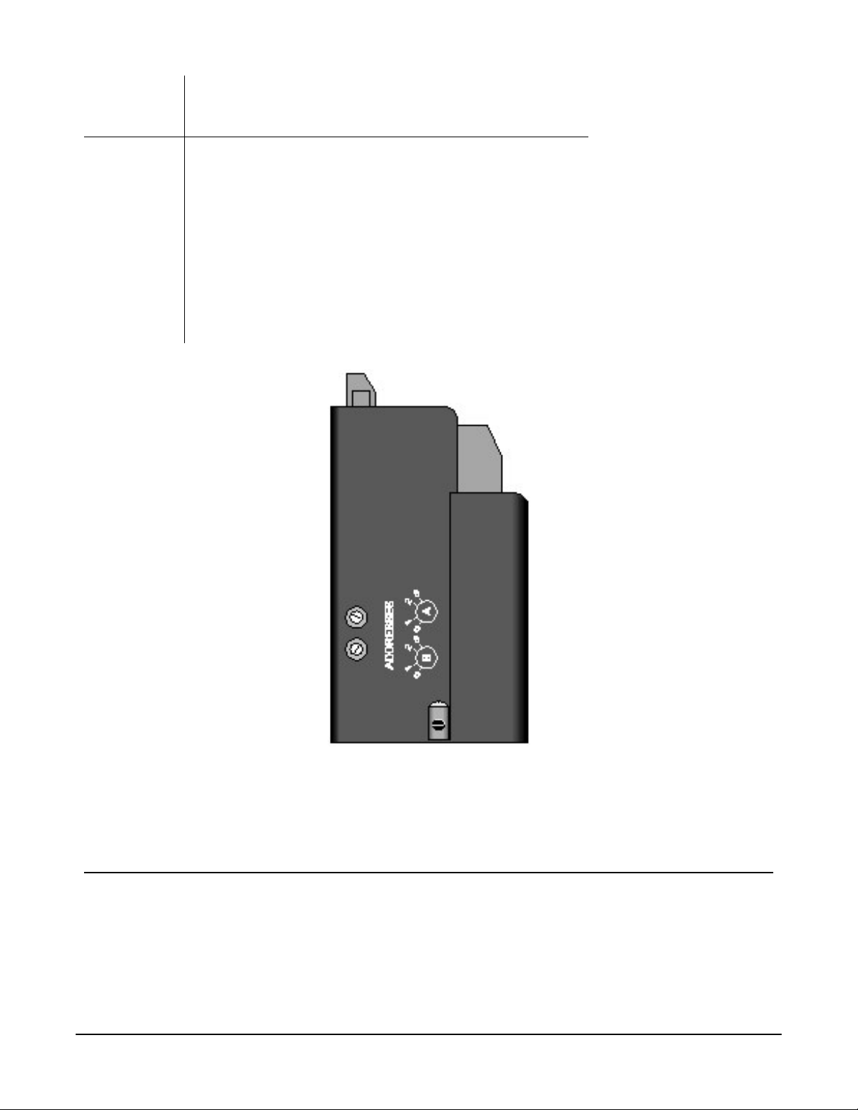
Each SDM-CD16AC can have 1 of 16 addresses. Shipped from the factory, the address is set at 00.
The following table shows switch position and the corresponding address (see FIGURE 5-1 (p. 8)).
SDM-CD16AC 16 Channel AC/DC Controller 7
Switch A
0 1 2 3
Switch B
0 00 01 02 03
1 10 11 12 13
2 20 21 22 23
3 30 31 32 33
Base 4 Address Matrix
(00, 01, 02 . . . 32, 33)
FIGURE 5-1. Addressing
6. Data logger programming
In CRBasic, the SDMCD16AC() instruction is used to control the SDM-CD16AC. Data loggers that
are programmed with CRBasic include the CR6, CR3000, CR1000X, CR800, CR850, and CR1000.
The SDMSpeed() instruction should also be used if the cable length is longer than 20ft.
SDM-CD16AC 16 Channel AC/DC Controller 8
Altri manuali per SDM-CD16AC
2
Indice
Altri manuali Campbell Controllori

Campbell
Campbell CR10 PROM Manuale utente

Campbell
Campbell SDM-CD16ACA Manuale utente

Campbell
Campbell SDM-CD16AC Manuale utente

Campbell
Campbell PS12LA Manuale utente

Campbell
Campbell SDM-CD16AC Manuale utente

Campbell
Campbell PS150 Manuale utente

Campbell
Campbell PS150 Manuale utente

Campbell
Campbell CR10 PROM Manuale per l'uso e la cura

Campbell
Campbell CH150 Manuale utente

Campbell
Campbell CH201 Manuale utente


