CanadianSolar CSI-WIFI-2 Manuale utente

Model: CSI-WIFI-2
Data Logger (WiFi) Quick Guide
(Version: V1.2 Release date: September, 2021)

1/ 14
Contents
1. Introduction ···················································································································································· 2
2. Notice for Use ················································································································································· 2
3. Electrical Connection ······································································································································ 2
4. Logger Status·················································································································································· 3
4.1 Checking Indicator light ··························································································································· 3
4.2 Normal operation status ·························································································································· 3
4.3 Abnormal States········································································································································ 4
5. Usage methods and notices for Reset button ····························································································· 5
5.1 Usage methods and key-press descriptions for Reset button······························································ 5
5.2 Notice for Reset button ···························································································································· 5
6. APP User Manual ············································································································································ 6
6.1 Download APP··········································································································································· 6
6.2 Registration ··············································································································································· 6
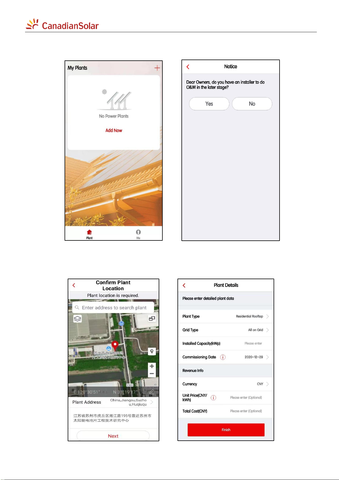
6.3 Create Plant··············································································································································· 7
6.3.1 Click [Add Now] to create a plant. Proceed as described below.··················································· 7
6.3.2 Confirm location·································································································································7
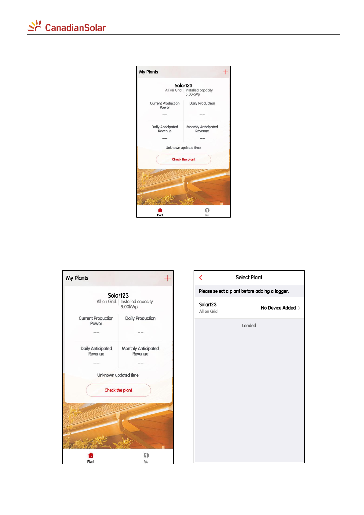
6.3.3 Check the plant··································································································································· 8
6.4 Add a device ·············································································································································· 8
6.4.1 Add Logger ········································································································································· 8
6.4.2 Select correlated devices ··················································································································· 9
7. WiFi Networking Configuration····················································································································· 9
7.1 Smart Link configuration························································································································ 10
7.1.1 Entering configuration mode·········································································································· 10
7.1.2 Connecting WiFi network················································································································· 10
7.2 AP configuration ····································································································································· 11
7.2.1 Entering configuration mode·········································································································· 11
7.2.2 Connecting WiFi network················································································································· 12
7.2.3 Abnormal States······························································································································· 13
ANNEX A REACH Declaration
ANNEX B CE & RoHS Declaration

2/ 14
1. Introduction
This Data Logger WiFi Stick is used to relay CSI Inverter data to CSI cloud data monitoring app platforms
– CSI Cloud & CSI Cloud Pro. Users can easily check device information by logging in to either of these
platforms.
This manual is only valid for the WiFi Stick type CSI-WIFI-2, produced by CSI Solar Co., Ltd.
2. Notice for Use
Warning
1. Please remove logger after power off;
2. Reset button supports direct press. Do not remove waterproof plug.
Notice
To ensure normal use of the device, before using it, be sure that:
1. The connected wireless router has uninterrupted internet access;
2. A WiFi-enabled mobile phone or a laptop computer are connected to this device for
parameter setting.
Notice
To ensure adequate communication quality, the device must be kept away from large
metal objects and any electrical device with strong magnetic fields, such as a microwave
oven, refrigerator, cordless phone, and PV panel.
Communication quality can also be affected by thick walls, concrete and lightning.
3. Electrical Connection
Connect the WiFi Stick to the communication port on the underside of the inverter.
Data Logger WiFi Stick installation:
1) Insert WiFi Stick to COM port;
2) Fasten the WiFi Stick in clockwise rotation.

3/ 14
3) Install and remove
4. Logger Status
4.1 Checking Indicator light
Lights
Implication
Status Description (All lights are single green lights.)
Communication
with router
1.Light off: Connection to the router failed;
2. 1s on, 1s off (slow flash): Connection to the router succeeded;
3. Light keeps on: Connection to the server succeeded;
4. 100ms on, 100ms off (fast flash): Distributing network fast.
Communication
with inverter
1. Light keeps on: Logger connected to the inverter;
2. Light off: Connection to the inverter failed;
3. 1s on, 1s off (slow flash): Communicating with inverter.
Logger running
status
1. Light off: Running abnormally;
2. 1s on, 1s off (slow flash): Running normally;
3. 100ms on, 100ms off (fast flash): Restore factory settings.
4.2 Normal operation status
Lights
Implication
Status Description
Connection to the server
succeeded.
NET light keeps on after the logger powered
on.
Logger running normally.
COM light keeps on.
Connection to the inverter
succeeded.
READY light flashes.

4/ 14
4.3 Abnormal States
When the data on platform is abnormal if the data logger is running, please check the table as below for
quick troubleshooting. If it still cannot be resolved or indicator lights status do not show in the table,
please contact Customer Support.
Note: Please using the following table query after power-on for 2mins at least.
Errors as indicated in the table below:
NET
COM
READY
Fault Description
Fault Cause
Suggestion
Any
state
OFF
Slow
flash
Abnormal
communication
with inverter.
1. loosen connection
between data
logger and inverter.
2.Inverter does not
match with data
logger's
communication
rate.
1.Remove the data logger and
install again.
2.Check inverter's
communication rate to see if it
matches with data logger's.
3.Long press Reset button for
5s, reboot data logger.
OFF
ON
Slow
flash
Abnormal
connection
between logger
and router.
1.Data logger does
not have a network.
2.Antenna abnormal
3.Router WiFi signal
strength weak.
1.Check if the wireless network
is configured.
2.Check the antenna, if there is
any damage or loose.
3.Enhance router WiFi signal
strength.
4.Long press Reset button for
10s, reboot data logger and
networking again.
Show
flash
ON
Slow
flash
Abnormal
connection
between logger
and router, or
abnormal
connection
between logger
and remote server.
1.Router networking
abnormal.
2.The server point of
logger is modified.
3.Server cannot be
connected.
1.Check if the router is access
to the network.
2.Check the router's setting, if
the connection is limited.
3.Contact our customer service
OFF
OFF
OFF
Power supply
abnormal.
1. Abnormal
connection between
data logger and
inverter.
2.Inverter power
insufficient.
3.Data Logger
abnormal.
1.Check the connection, remove
the data logger and install
again.
2.Check inverter output power.
3.Contact our customer service.
Fast
flash
Any
state
Any
state
SMARTLINK
networking status.
Normal
1.Exit automatically after 5mins.
2.Long press Reset button for
5s, reboot data logger.
3.Long press Reset button for
10s, restore factory settings.
Any
state
Any
state
Fast
flash
Restore factory
settings.
Normal
1.Exit automatically after 1mins.
2.Long press Reset button for
5s, reboot data logger.
3.Long press Reset button for
10s, restore factory settings.

5/ 14
5. Usage methods and notices for Reset button
5.1 Usage methods and key-press descriptions for Reset button
Key-press
Status Description
Light Status
Short press 1s
SMARTLINK rapid networking status.
NET light ashes fast for 100ms.
Long press 5s
Rebooting the data logger
All lights are extinguished immediately.
Long press 10s
Rebooting the data logger
1. All lights are extinguished after 4s.
2. READY light ashes fast for 100ms
5.2 Notice for Reset button

6/ 14
6. APP User Manual
6.1 Download APP
CSI Cloud
(end user)
CSI CloudPro
(business)
6.2 Registration
Click [Register] to create new account. Use your email to register.

7/ 14
6.3 Create Plant
6.3.1 Click [Add Now] to create a plant. Proceed as described below.
6.3.2 Confirm location
Confirm the location of the plant and complete the related details on the next page, and then click [Finish]
to complete the plant.

8/ 14
6.3.3 Check the plant
Now you can see the plant you just created on the home page.
Click the [Check the plant] button to view detailed data for the plant.
6.4 Add a device
6.4.1 Add Logger
Click the [+] button in the upper right corner of the home page, select Add a Logger, and select the plant
where you want to add the device in the next page.

9/ 14
Choose to scan the barcode of the collector, or directly enter the SN number below the barcode to add
it, then click the [Add] button to go to the next page.
6.4.2 Select correlated devices
On this page, you can stipulate how the logger selects the device associated with it. The default mode is
“Automatic Selection”. If you do not have special requirements, please click the [Done] button to confirm.
After the confirmation is completed, the logger will be added to the plant.
7. WiFi Networking Configuration
If your logger is a Wi-Fi module, it will need to be networked for normal use.
On the specific plant page, click the [...] button in the upper right corner, select [Device] to enter the
device page, select the logger to be configured, and click the [Device networking] button to configure.
Indice
Altri manuali CanadianSolar Registratore di dati


