Caraudio-Systems c.LOGiC C2-MFD2 Manuale utente

Version 01.09.2011 C2-MFD2
c.LOGiC-Interface
C2-MFD2
For navigation systems
Volkswagen MFD2/RNS2
Skoda Nexus
Only for vehicles WITHOUT factory rear-view camera
Product features
• full plug and play multimedia interface
• 2 AV-inputs with separate IR-control channel
• control of after-market devices, e.g. DVB-T tuner, DVD-player, DVD-changer, …
• after-market rear-view camera input
• automatic switching to rear-view camera input (only from interface mode)
• rear-view camera power (+12V max 1A)
• rear-seat-entertainment AV-output
• power on remote out trigger signal (+12V max 1A) to switch on connected devices
• video-in-motion

Version 01.09.2011 C2-MFD2
Page1
Contents
1. Prior to Installation
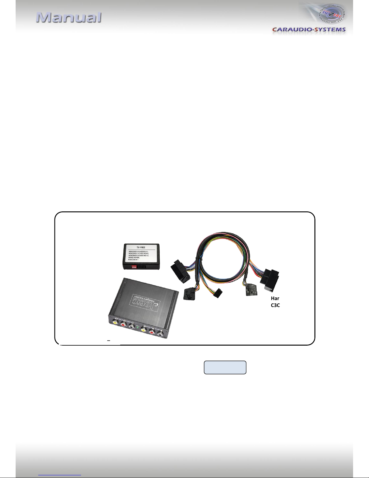
1.1. Delivery contents
1.2. Check compatibility of vehicle and accessories
1.3. Setting the dip switches of the CAN-box TV-400
1.4. Setting the dip switches of the Interface-box C2C-M200
1.4.1. Automatic switching to rear-view camera
1.4.2. Deactivating c.LOGiC AV2-input
2. Connection schema
3. Installation
3.1. Interconnecting Interface-box, CAN-box and harnesses
3.2. Connections to head-unit
3.3. Connecting peripheral devices
3.3.1. AV-source(s)
3.3.2. Installing AV-source’s IR-sensor additionally
3.3.3. After-market rear-view camera
3.3.4. After-market rear-seat-entertainment
4. Operation
4.1. Activation of the video-in-motion function
4.2. Selecting the c.LOGiC as current AV-source
4.3. Switching between AV1 and AV2
4.4. Assigning device controls
4.5. Button assignment table
4.6. Picture settings
5. Specifications
6. Technical support
Appendix A –Device control table

Version 01.09.2011 C2-MFD2
Page2
Legal Information
By law, watching moving pictures while driving is prohibited, the driver must not be
distracted. We do not accept any liability for material damage or personal injury resulting,
directly or indirectly, from installation or operation of this product. This product should only
be used while standing or to display fixed menus or rear-view-camera video when the
vehicle is moving, for example the MP3 menu for DVD upgrades.
Changes/updates of the vehicle’s software can cause malfunctions of the interface. We offer
free software-updates for our interfaces for one year after purchase. To receive a free
update, the interface must be sent in at own cost. Labor cost for and other expenses
involved with the software-updates will not be refunded.
1. Prior to installation
Read the manual prior to installation. Technical knowledge is necessary for installation. The
place of installation must be free of moisture and away from heat sources.
1.1. Delivery contents
If remote function for the connected devices shall be used, additional an IR-
remote cable and Y-adapter are needed, see chapter AV-source(s).
CAN-box
TV-400
HW_____
SW _____
Take down the SW-version and HW-version of the interface boxes, and store this
manual for support purposes.
Interface-box
C2C-M200
HW_____ SW_____
Harness
C3C-VW02

Version 01.09.2011 C2-MFD2
Page3
dip switches
Interface-box
1.2. Check compatibility of vehicle and accessories
1.3. Setting the dip switches of the CAN-box TV-400
1.4. Setting the dip switches of the Interface-box C2C-M200
The default dip switch settings of the Interface-box
need to be changed ONLY if an after-market
rear-view camera shall be connected or if the AV2
of the c.LOGiC shall be deactivated. The dip
switches are located inside the Interface-box.
For changes it is necessary to open the box.
Default settings are:
Dip1 = ON, dip2 = OFF, dip3 = OFF
Note: Instead of dip switches, there might be jumper 1 to 3.
1.4.1. Automatic switching to rear-view camera
If an after-market rear-view camera shall be connected, in order
for the c.LOGiC to automatically switch to its camera input
on engaged reverse gear,
set dip2 = ON (up).
1.4.2. Deactivating c.LOGiC AV2-input
If only one AV-source shall be connected to the c.LOGiC, we
recommend to disable the AV2-input, to avoid customers switching by
mistake to black/no picture of the AV2-input. In order to disable the
AV2-input of the c.LOGiC,
set dip1 = OFF (down).
Requirements
Vehicle Volkswagen and Skoda
Navigation MFD2/RNS2 or Nexus navigation
Limitations
Factory-TV-tuner Must NOT be installed.
All vehicles dip 1 ON, dip 2 OFF, dip 3 OFF

Version 01.09.2011 C2-MFD2
Page4
2. Connection schema

Version 01.09.2011 C2-MFD2
Page5
3. Installation
Switch off ignition and disconnect the vehicle’s battery! If according to factory rules
disconnecting the battery has to be avoided, it is usually sufficient to put the vehicle is
sleep-mode. In case the sleep-mode does not show success, disconnect the battery with a
resistor lead.
Place of installation is behind the head-unit.
3.1. Interconnecting Interface-box, CAN-box and harnesses
Plug harness C3C-VW02 into 8pin Molex of CAN-box TV-400.
Plug harness C3C-VW02 into 14pin Molex of Interface-box C2C-M200.
Plug female 18pin AMP-connector of C3C-VW02 into male 18pin AMP-socket of
Interface-box C2C-M200.

Version 01.09.2011 C2-MFD2
Page6
3.2. Connections to head-unit
Remove the head-unit from the dash-board.
Transfer female Quadlock connector from the back of the head-unit to male
Quadlock connector of harness C3C-VW02.
Plug female Quadlock connector of C3C-VW02 into male Quadlock socket of
head-unit.
Plug female 18pin AMP-connector of C3C-VW02 into male 18pin AMP-socket of
head-unit.
Note: If the 18pin AMP-socket of the head-unit is already occupied, the vehicle probably has
a factory rear-view camera or a factory TV-tuner. In case of a factory tuner, it must be
uninstalled: disconnect the female 18pin AMP-connector of the factory harness and
disconnect all wires from the factory TV-tuner. In case of a factory rear-view camera you
have ordered/received the wrong product, call for support.

Version 01.09.2011 C2-MFD2
Page7
3.3. Connecting peripheral devices
It is possible to connect up to 2 after-market AV-sources, after-market rear-view camera and
rear-seat-entertainment to the c.LOGiC interface.
Before final installation of the peripheral devices, we recommend to test-run the c.LOGiC
functions to detect incompatibility of vehicle, navigation, factory accessories or peripheral
devices as soon as possible.

Version 01.09.2011 C2-MFD2
Page8
3.3.1. AV-source(s)
The c.LOGiC interface has the possibility to connect and remotely control by navigation
buttons up to 2 pre-programmed devices. The device list in the device control table
(Appendix A) shows the pre-programmed remote channels and the related IR-remote cables
STA-xxx which must be ordered separately for the control of the device.
Using the respective STA-xxx IR-control cable, interconnect the blue (yellow) female
3pin AMP connector of harness C3C-VW02 and the IR-port of the AV-source 1 (AV-
source 2).
Using an RCA-cable, interconnect the female RCA-port AV1 (AV2) of the Interface-box
C2C-M200 with the AV-output of the AV-source 1 (AV-source 2).
The pink ACC-output wire (+12V max 1A) of harness C3C-VW02 can be connected to
the ACC-input wires of the connected device to switch it on. It carries +12V when the
head-unit is running.

Version 01.09.2011 C2-MFD2
Page9
3.3.2. Installing AV-source’s IR-sensor additionally
Additionally to the control via OEM navigation, it is possible to install the original IR-sensor
of a connected device. By using the respective Y-adapter (e.g. STA-Y35MM or STA-RJ12) for
the IR-Port of the connected device, the controls of navigation AND device’s IR-sensor can be
connected and used simultaneously. Installation of the IR-sensor is recommended as the
controls via navigation are limited, and not all functions may be covered.
3.3.3. After-market rear-view camera
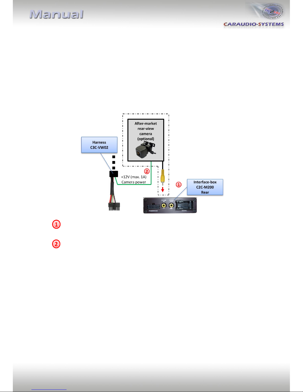
Connect the video RCA of the after-market rear-view camera to female
RCA connector R-CAM IN of Interface-box C2C-M200.
Connect the green wire of C3C-VW02 to the camera power supply (max. 1A)
The green wire is high (+12V) when reverse gear is engaged.
Indice
Altri manuali Caraudio-Systems Elettronica per automobili