Cargo 211165 Manuale utente

Instruction Manual
Bedienungsanleitung
Manual De Instruction
Instruktionsmanual
Användarhandbok
Vedpak 223_Version 1_09.2019
211165
Manuale Utente
Gebruikshandleiding
Instrukcja użytkowania
Manual de instrucciones
ES

Vedpak 223_Version 1_09.2019
211165
Multi-Function Automobile Tester
I. SPECIFICATION
• POWER SOURCE: 12-24V DC SYSTEM
• DC VOLTAGE MEASUREMENT RANGE: 0-70V
• DC CURRENT MEASUREMENT RANGE: 0-5A
• FREQUENCY MEASUREMENT RANGE: 0-300KHz (SQUARE WAVE)
• RESISTANCE MEASUREMENT RANGE: 0-200KΩ
• WORKING TEMPERATURE: 0-50°C
• STORAGE TEMPERATURE: -10-60°C
• WORKING HUMIDITY: ≤ 85%
• MEASURED TEMPERATURE RANGE: -50 – 500°C / -58-932°F
(ERROR will be displayed when tester is not connected with temperature probe.)
II. PRODUCT DESCRIPTION
Temperature
Measurement
Temp. Sensor
Testing Probe (4)
Thermocouple (13)
(OPTIONAL)
Testing Temp.
≤150°C / 302°F
≤500°C / 932°F

3Vedpak 223_Version 1_09.2019
211165
(1) SCREEN
(2) ILLUMINATION
(3) POLARITY INDICATION LIGHT
Positive: RED
Negative: GREEN
(4) TESTING PROBE
Available to take o
(5) POWER PROVIDING SWITCH
(6) MODE BUTTON
a. Short Press: To switch the measurement function
b. Long Press: To switch between °C and °F
(7) FUSE BOX CAP
Open it to change the fuse
(8) FUSE
Fixed auto-recover fuse is 5A, replaceable fuse can be any.
The tester will use the smallest value to protect the circuit.
For example, if Fixed auto-recover fuse is 5A, and replaceable fuse is 10A, the
current limitation will be 5A.
If Fixed auto-recover fuse is 5A, and replaceable fuse is 1A, the current limita-
tion will be 1A.
(9) POWER CLIPS
(10) CIGARETTE LIGHTER PLUG
(11) AUXILIARY GROUND CONNECTOR
(12) ACCESSORY
c. Connector
d. Wire Piercing Probe
e. Long Testing Probe
(13) THERMOCOUPLE (OPTIONAL)
(14) 6m EXTENSION CABLE (OPTIONAL)

211165
4Vedpak 223_Version 1_09.2019
III. OPERATION
Shortly press MODE button to switch function between DC Voltage, Resistance,
Current, signal frequency and voltage.
Connect the red clip to positive of battery, and black clip to negative of battery.
Auxiliary ground connector is used to connect with the negative of testing
object when it is necessary.
1) DC Voltage Measurement - External Voltage Test
A. DC Voltage Measurement
B. Temperature Measurement
(sensed from thermocouple)
C. DC Voltage Value
D. Max Voltage Value
E. Min Voltage Value
Temp.
CAUTION: Do not press “Power Providing Switch” during DC measurement.
(1) Short press MODE button to switch function to DC Voltage Measurement.
(2) Connecting the testing probe and auxiliary ground connector to the two polarity
of the testing object.
(3) Read the voltage value from the screen.
(4) Read the max and min value of present testing voltage.
(5) If there is a K-type thermocouple sensor on testing
probe, the temperature will be displayed on LCD.
If there is no sensor, the temperature can be
measured by external K-type thermocouple.
2) Signal Frequency and Max/Min Voltage Measurement
A. Frequency Measurement
B. Average Voltage Value
C. Max Voltage Value
D. Min Voltage Value
Frequency
Unplug

211165
5Vedpak 223_Version 1_09.2019
(1) Short press MODE button to switch function to signal frequency and
Voltage Measurement.
(2) Connecting the auxiliary ground connector to the negative or ground, and probe to
the positive or the testing target.
(3) Read the average voltage value from the screen.
(4) Read the max and min value of present testing voltage.
(5) Read the frequency value of present testing signal.
3) Resistance Measurement
Battery
A. Resistance Measurement
B. Max Continuity Value
C. Resistance Value
D. Battery Voltage
(1) In order to prevent electrical hazard, please disconnect the power connection
and resistor, and read the value from the screen.
(2) Short press MODE button to switch function to Resistance Measurement.
(3) Connecting the testing probe and auxiliary ground connector to the two side of
the resistor, and read the value from the screen.
(4) Continuity Test: If the resistance is less than 30 ohms, the buzzer will buzz and
the negative polarity indicator light up (Green Color).
(5) Read the battery value.
4) Testing Power Providing
(This function can be activated any time when the POWER PROVIDING SWITCH
has been pressed.)
(1) Press POWER PROVIDING SWITCH forward, the positive voltage will be sent to the
testing probe, and positive polarity indicator will light up (Red Color).
(2) Press POWER PROVIDING SWITCH backward, negative voltage will be sent to the
testing probe, and negative polarity indicator will light up (Green Color).
(3) The providing voltage value will depend on the supply voltage level. For example,
the providing voltage will be 12V as supply voltage is a 12V battery.
Continuity
211165
6Vedpak 223_Version 1_09.2019
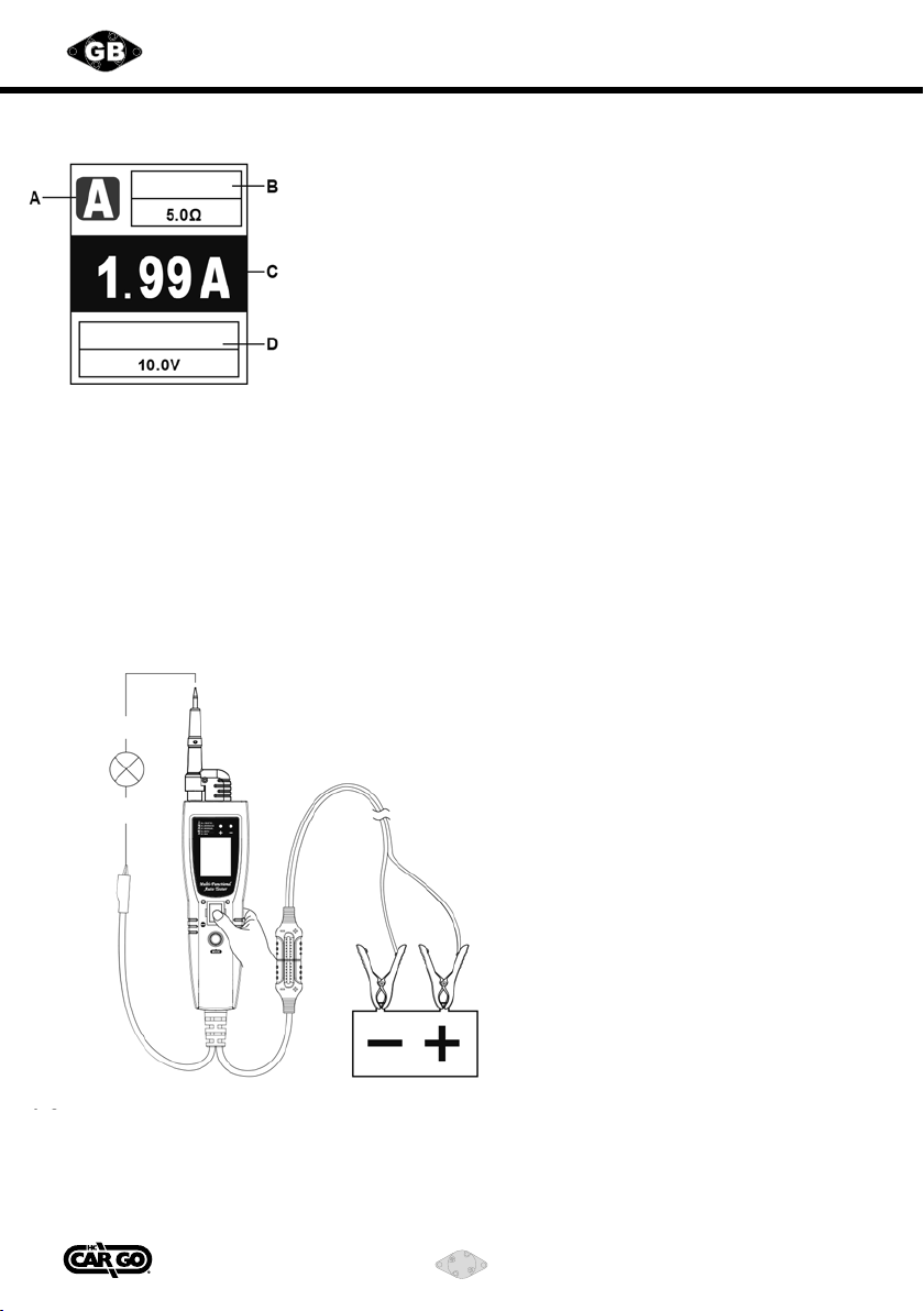
5) DC Current Measurement
Battery
Continuity
A. Current Measurement
B. Resistance of Testing Object
C. Current Value
D. Battery Voltage
1.1 Providing Current to External
Short press “MODE” button to switch the function to DC Current Measurement.
(1) Connecting the testing probe to the positive of testing load, and auxiliary ground
connector to the negative of testing load. Press the POWER PROVIDING SWITCH
forward.
(2) Read the current value from the screen.
(3) Read the resistance of testing object.
(4) Read the battery value.
1.2
(1) Connecting the testing probe to the negative of testing load, and auxiliary ground
connector to the ground of the circuit. Press the POWER PROVIDING SWITCH
backward.
(2) Read the current value from the screen.
Positive
Negative
Load

211165
7Vedpak 223_Version 1_09.2019
IV. CAUTION
During the power providing, If the short circuit protection has activated, the
PPTC fuse will jump o, and it will self-recover within about 60 seconds.
Please do not touch the testing probe when short circuit protection is activated
because high temperature generally comes with short circuit.
V. ACCURACY
DC Voltage 0–70V±(2%+2 digits)
Signal frequency and voltage Frequency 0–300KHz±(1%+1 digits)
Resistance 0-200K±(5%+3 digits)
Current 0–5A ±(3%+10 digits)
Temperature
-50°C~500°C -58°F~932°F
-50°C~-20°C (±1.5+4 digits) -58°F~-4°F (±1.5+6 digits)
-20°C~500°C (±1.5+3 digits) -4°F~932°F (±1.5+5 digits)
Positive
Negative
Load
BATTERY

211165
8Vedpak 223_Version 1_09.2019
Automobiltestgerät mit mehreren Funktionen
I. TECHNISCHE DATEN
• STROMQUELLE: STROMVERSORGUNG 12-24 V DC
• GLEICHSTROM-SPANNUNGSMESSBEREICH: 0-70 V
• GLEICHSTROM-SPANNUNGSMESSBEREICH: 0-5 A
• FREQUENZMESSBEREICH: 0-300 kHz (RECHTECKWELLE)
• WIDERSTANDSMESSBEREICH: 0-200 kΩ
• BETRIEBSTEMPERATUR: 0-50 °C
• LAGERTEMPERATUR: -10 bis +60 °C
• BETRIEBSFEUCHTIGKEIT: 85 %
• MESSTEMPERATURBEREICH: -50 – 500 °C (FEHLER wird angezeigt, wenn das
Testgerät nicht mit Temperaturfühler verbunden ist.)
II. PRODUKTBESCHREIBUNG
Temperatur-
messung
Temp. Sensor
Testsonde (4)
Thermoelement (13)
(OPTIONAL)
Testtemperatur
≤150 °C
≤500 °C

211165
9Vedpak 223_Version 1_09.2019
(1) BILDSCHIRM
(2) BELEUCHTUNG
(3) POLARITÄTSANZEIGE
Positiv: ROT
Negativ: GRÜN
(4) TESTSONDE
Abnehmbar
(5) STROMSCHALTER
(6) MODUS-TASTE
a. Kurze Betätigung: Einschalten der Messfunktion
b. Lange Betätigung: Umschaltung zwischen °C und °F
(7) SICHERUNGSKASTENDECKEL
Önen zum Austausch der Sicherung
(8) SICHERUNG
Stationäre selbstrückstellende Sicherung mit 5 A, austauschbare Sicherung
beliebig
Das Testgerät verwendet den kleinsten Wert zum Schutz der Schaltung.
Wenn die stationäre selbstrückstellende Sicherung z. B. 5 A und die austausch-
bare Sicherung 10 A hat, beträgt die Strombegrenzung 5 A.
Wenn die stationäre selbstrückstellende Sicherung 5 A und die austauschbare
Sicherung 1 A hat, beträgt die Strombegrenzung 1 A.
(9) STROMKLEMMEN
(10) ZIGARETTENANZÜNDER
(11) ZUSÄTZLICHER MASSESTECKER
(12) ZUBEHÖR
c. Stecker
d. Leiter Stecksonde
e. Lange Testsonde
(13) THERMOELEMENT (OPTIONAL)
(14) 6 m VERLÄNGERUNGSKABEL (OPTIONAL)

211165
10 Vedpak 223_Version 1_09.2019
III. BETRIEB
Um zwischen den jeweiligen Betriebsmodi zu wechseln, die Taste „MODE“ kurz drücken
(Wechsel zwischen: Gleichspannung, Widerstand, Strom, Frequenz, Wechselspannung).
Die rote Klemme mit dem Pluspol der Batterie und die schwarze Klemme mit dem Minuspol der
Batterie verbinden.
Der zusätzliche Massestecker dient bei Bedarf zur Verbindung mit dem Minuspol des Prüfobjekts.
1) Gleichstrom-Spannungsmessung - externer Spannungstest
A. Gleichstrom-Spannungsmessung
B. Temperaturmessung (vom Thermoelement erfasst)
C. Gleichstrom-Spannungswert
D. Höchstspannungswert
E. Mindestspannungswert
Temp.
ACHTUNG: Während der Gleichstrom-Spannungsmessung nicht den Stromschalter
betätigen.
(1) Die MODUS-Taste kurz zur Umschaltung auf Gleichstrom-Spannungsmessung
betätigen.
(2) Anschluss der Prüfsonde und des zusätzlichen
Massesteckers an die beiden Pole des Prüfobjekts
(3) Den Spannungswert auf dem Bildschirm ablesen.
(4) Den Höchst- und Mindestspannungswert der aktuellen
Prüfspannung ablesen.
(5) Wenn sich ein Thermoelementsensor vom Typ K an
der Prüfsonde bendet, erscheint die Temperatur in
der LCD-Anzeige. Wenn kein Sensor vorhanden ist, kann die
Temperatur mit einem externen Thermo-element vom Typ K gemessen werden.
2) Signalfrequenz sowie Höchst- und Mindestspannungsmessung
A. Frequenzmessung
B. Durchschnittswert Spannung
C. Höchstspannungswert
D. Mindestspannungswert
Frequenz
Stecker
abziehen.
Indice
Lingue:
Altri manuali Cargo Tester di circuito

Manuali Tester di circuito popolari di altre marche

IDEAL
IDEAL 61-534 Manuale utente

Kusam-meco
Kusam-meco KM 1812EL Manuale utente

MGE UPS Systems
MGE UPS Systems Galaxy 5000 Manuale utente

YOKOGAWA
YOKOGAWA MY10 Manuale utente

Power Probe Tek
Power Probe Tek PRO SERIES THE MAESTRO Manuale utente

Gossen MetraWatt
Gossen MetraWatt DUSPOL expert 1000 Manuale utente


