CarNetix PSU-PC12 Istruzioni operative

CarNetix PSU-PC12 V1.1 Installation Manual
CarNetix PSU-PC12 DC-DC Power Supply
(applies to Version 1.0+ hardware)
Installation and Operation of the PSU-PC12 with the Xenarc SC3
Version 1.1
June 1, 2006
- 1 -

CarNetix PSU-PC12 V1.1 Installation Manual
Table of Contents
1.0 PSU-PC12 Installation Instructions................................................................................................4
1.1 Overview..................................................................................................................................... 4
1.2 Features.......................................................................................................................................6
2.0 Installing the PSU-PC12................................................................................................................. 7
2.1 Before You Begin.......................................................................................................................7
2.2 Setting the Jumpers.....................................................................................................................8
JP1 Jumper Settings...................................................................................................................... 9
JP3 Jumper Settings (+5V Always ON)....................................................................................... 9
JP4 Jumper Settings (Secondary Output Control)........................................................................9
2.3 Connecting the Wires................................................................................................................11
2.4 Optionally Connecting the Xenarc LCD Screen.......................................................................14
3.0 Using the Pulse Start Feature........................................................................................................17
3.1 Pulse Start Connections............................................................................................................17
3.2 Pulse Start Operation................................................................................................................ 17
3.2.1 What is a pulse?................................................................................................................. 17
3.2.2 Starting the PSU with a pulse............................................................................................ 18
3.2.3 Stopping the PSU with a pulse ..........................................................................................18
3.2.4 Prolonging the Shutdown Delay State...............................................................................18
3.2.5 Shutting down the PSU with double pulses.......................................................................18
3.2.6 Ignition Override................................................................................................................18
4.0 PSU-PC12 Startup/Shutdown Controller......................................................................................19
4.1 Hibernate/Standby Operation ...................................................................................................19
4.2 SSC Operation States................................................................................................................ 19
4.2.1 Idle State............................................................................................................................ 19
4.2.2 RunDelay State..................................................................................................................19
4.2.3 Bootup Lockout State ........................................................................................................ 20
4.2.4 Run State............................................................................................................................20
4.2.5 Shutdown Delay State........................................................................................................20
4.2.6 Shutdown Sequence State..................................................................................................20
4.2.7 Forced Shutdown State......................................................................................................21
4.3 Fault Indicator LEDS................................................................................................................21
5.0 Conditions of Use ......................................................................................................................... 24
- 2 -

CarNetix PSU-PC12 V1.1 Installation Manual
Summary of Notices & Disclaimers
CarNetix limited warranty is contingent upon proper and normal use and installation, and
does not cover damage due to external causes, including but not limited to, accident,
problems with electrical power, improper installation techniques or materials, liquids,
chemicals, oxidation, corrosion, exposure to the elements, servicing not authorized by
CarNetix, usage not in accordance with product instructions or specifications, failure to
perform required preventive maintenance, and problems caused by use of parts and
components not supplied by CarNetix.
CarNetix makes no express warranties or conditions beyond those stated in this warranty
statement. CarNetix disclaims all other warranties and conditions, express or implied,
including without limitation implied warranties and conditions of merchantability and fitness
for a particular purpose. Some states do not allow limitations on how long an implied
warranty lasts, so the above limitation may not apply to you.
CarNetix does not accept liability beyond the remedies set forth in this warranty statement
or liability for incidental or consequential damages, including without limitation any liability
for products not being available for use or for lost data or software.
CarNetix full warranty and return policies are stated in Section 6 at the end of this
document.
- 3 -

CarNetix PSU-PC12 V1.1 Installation Manual
1.0 PSU-PC12 Installation Instructions
NOTE: This manual and feature set apply to Rev 1.0 and above of the printed circuit board (PCB).
The PCB revision number is printed on the top of the PCB in white lettering. Please make sure you
are using the correct manual for the correct product revision.
1.1 Overview
The PSU-PC12 is a 90 watt intelligent DC-DC power regulator designed to provide safe, reliable
power to the Xenarc SC3.
Figure 1 CarNetix PSU-PC12
The PSU-PC12 provides two outputs. The primary output is +12V and can provide up to 6.3 amps
(75 Watts). The secondary output is +5V to power USB devices (such as the Audigy 2NX sound
USB sound card) with up to 3 amps (15 Watts). The PSU-PC12 can accept battery input as low as 7
volts under full load (90 watts) during cranking while providing a well-regulated output so that your
Xenarc SC3 does not crash.
- 4 -

CarNetix PSU-PC12 V1.1 Installation Manual
The PSU-PC12 includes an internal relay to control the ACPI interface of the Xenarc SC3. No more
soldering an external relay between the PSU-PC12 and the Xenarc SC3!
The PSU-PC12 includes all of the sophisticated features of its predecessors (P1260 and P1280) such
as Startup/Shutdown controller, Pulse Start (remotely start the PSU-PC12 with door locks, car alarm,
or wireless device), and DelayON (prevents speaker "thump" during booting). The PSU-PC12 fully
and safely supports "Standby" mode and will automatically shut itself down (by detecting excess
current drain) if the Xenarc SC3 fails to properly go into Standby mode.
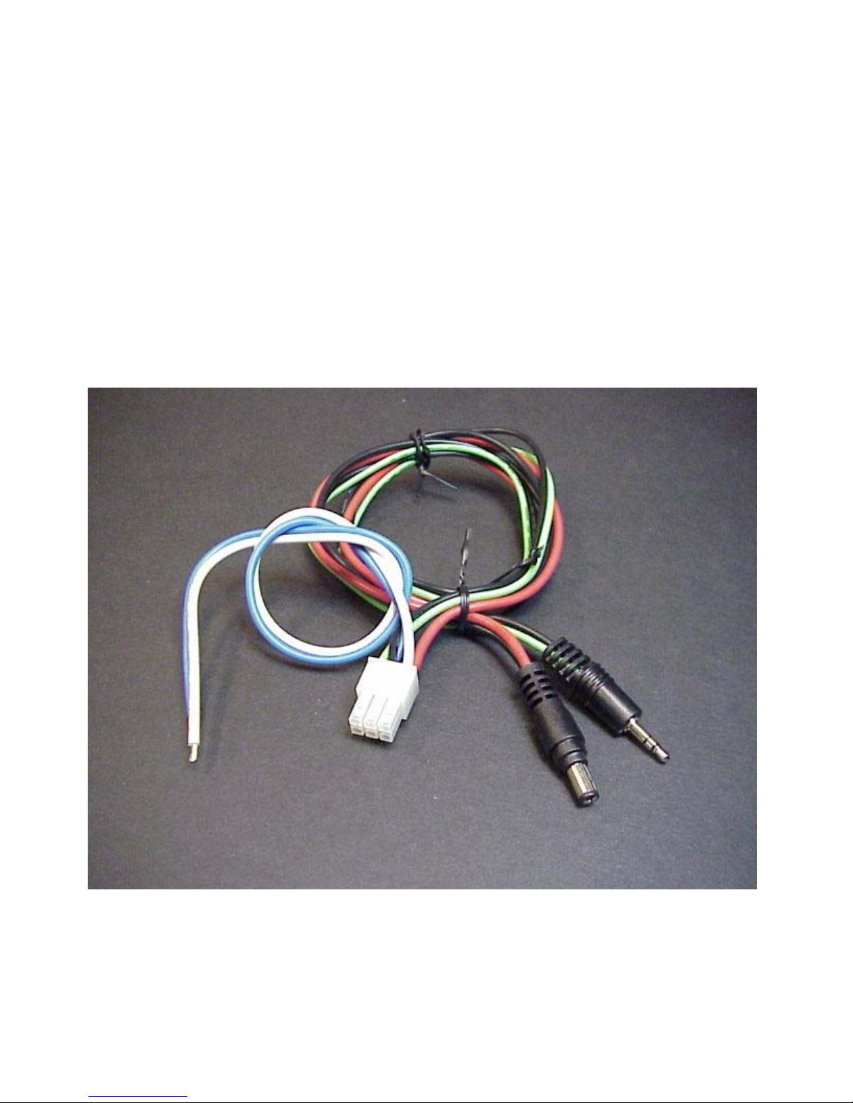
The PSU-PC12 includes a power cable for “plug and play” installation with the Xenarc SC8
computer. This simplifies the installation and provides a safe, reliable connection for your Xenarc
SC3.
Figure 2 PSU-PC12 Power Cable
- 5 -

CarNetix PSU-PC12 V1.1 Installation Manual
1.2 Features
•90 Watt Dual Output Regulator
•Main output of +12V @ 6.3 Amps
•Secondary output of +5V @ 3 Amps
•Survives Engine Cranking under full load over entire temperature range
•Includes sophisticated Startup/Shutdown Controller
•INCLUDES INTERNAL ACPI RELAY Xenarc PC compatibility
•Includes sturdy aluminum chassis with variable speed fan suitable for car
environment
•Field upgradeable flash microprocessor
•Low battery monitor prevents drained battery, even during Standby
•"Anti Thump" delayed remote control for audio amplifiers
•Remote "Pulse Start" from wireless device or car alarm/remote start system
•Over current protection on both outputs with graceful forced shutdown of main
output
•Powers both your Xenarc SC3 AND your screen or USB devices
•Full, safe support for Windows Standby mode including auto shutdown if PC fails to
shutdown
•Over voltage surge suppression on battery input for protection of harsh automotive
environment
•User replaceable fuse on battery input to protect your car from internal short circuits
•Very compact design measuring just 4.6" x 3.25" x 1.75" (L x W x H) or 117mm x 83mm x
45mm
- 6 -

CarNetix PSU-PC12 V1.1 Installation Manual
2.0 Installing the PSU-PC12
2.1 Before You Begin
Before you begin the installation, make sure you take the time to read through these instructions.
The PSU-PC12 is a sophisticated, microprocessor-based device. Please read these instructions
carefully and contact us either in our Support Forum (www.carnetix.com/forum) or via email
([email protected]) if you have any questions or problems.
It is assumed that you have a basic to advanced understanding of electronics. It would be helpful,
and is highly recommended (especially if you plan to get much further involved in CarPCs) that you
purchase, as a minimum, a simple VOM (volt-ohm meter) or DMM (Digital Multi-Meter). These
devices are inexpensive (starting around $20) and will save you and me a great deal of time. They
can be purchase over the web or at your local retail electronics store (Radio Shack, Home Depot,
some hardware stores, some auto parts stores).
Whether you plan to use the on-board Startup/Shutdown Controller (SSC) or not, please read the
section describing its operation first, before attempting to install the PSU-PC12. The SSC will affect
the power turn-on and turn-off operation whether you use its features or not.
Installation of the PSU-PC12 consists of :
•Setting the Jumpers
•Connecting the Wires.
- 7 -

CarNetix PSU-PC12 V1.1 Installation Manual
2.2 Setting the Jumpers
There are 3 user settable jumpers on the PSU-PC12. Below is a picture of their location on the
board. You will need to remove the 4 screws that hold the lid, remove the lid, and disconnect the fan
wire to get access the jumpers. Once you have selected your desired jumper positions, replace the
fan wire (note polarity of connector), replace the lid, and replace the 4 lid screws. Be careful not to
pinch the wire or let the fan wire touch the blades of the fan as your replace the lid.
Jumper Functions
JP1 Pulse Start Input
Shutdown Delay Time
Hibernate/Standby
DelayOn Option
JP3 +5V Always On
JP4 Secondary Output Control
JP-3JP-4JP-1 Figure 3 Jumper Location
- 8 -

CarNetix PSU-PC12 V1.1 Installation Manual
JP1 Jumper Settings
Below is a table with the jumper selectable options for JP1. To move a jumper from its factory
default (open) position, use a pair of tweezers or needle nose pliers. Be careful to place the jumper in
the correct position or erratic behavior could result. Double-check your settings before replacing the
lid.
JP1 Jumper Pin Assignments
Pins
1-2 3-4 5-6 7-8 9-10
Function Pulse Start
Input
Shutdown
Delay
Time
Hibernate/
Standby Not Used DelayOn
Option
Open
(default)
Connect to
external
contact
closure
6 Seconds Hibernate Not Used DLYON
follows IGN
Jumpered
Connect to
external
contact
closure
15 minutes Standby Not Used DLYON
follows PSU
Table 1 JP1 Settings
JP3 Jumper Settings (+5V Always ON)
For those users who want to keep +5V USB devices powered even when the Xenarc SC3 is OFF or
in Standby, you can jumper Pin1 to Pin 2 on JP3. This will keep the +5V regulator ON at all times,
even if the PSU-PC12 is OFF. Use caution when using this jumper position since it may cause your
battery to drain quickly.
JP4 Jumper Settings (Secondary Output Control)
The JP4 jumper gives you the flexibility to use the Secondary Output in different ways depending
upon your Xenarc SC3 system configuration. The Secondary Output can be turned on or off based
on two different control signals: 1) DLYON or, 2) the signal that controls the Primary Output (PRI
OUT).
•DLYON
Jumpering DLYON will turn your Secondary Output ON or OFF with the DLYON signal. This
means that your Secondary Output will come on 3 seconds after your Primary Output comes ON,
and will go off when you turn your ignition switch OFF.
- 9 -

CarNetix PSU-PC12 V1.1 Installation Manual
•PRI OUT
Jumpering PRI OUT will make the Secondary Output follow the control used to turn ON and OFF
the Primary Output. Thus, when the Primary Output is ON, the Secondary Output will also be ON. If
the Primary Output is OFF, the Secondary Output will be OFF.
This setting is affected by the jumper setting of the Shutdown Delay jumper on JP1. If you have set
the Shutdown Delay jumper to the default position (6 seconds), both the Primary and Secondary
Outputs will be turned OFF 6 seconds after the Ignition is turned OFF. If you have set the Shutdown
Delay jumper for 1 minutes, both the Primary and Secondary Outputs will remain ON for 1 minutes
after the Ignition is turned off. This setting is useful for keeping certain USB devices powered
during the Shutdown Delay time. For example, if you use the Secondary Output to power your USB
sound card and you want to keep your sound card powered during the Shutdown Delay time
(1minutes), then set the jumper JP4 for PRI OUT. Another application might be to keep a USB WiFi
card powered during Shutdown Delay for file transfer.
Follows PRI OUT
Follows DLYON
Once the jumper selections have been made you may begin installing the wiring to connect the PSU-
PC12 to your car’s electrical system, and to your Xenarc SC3.
- 10 -
Indice
Altri manuali CarNetix Alimentazione elettrica