Casio Cassiopeia A-10 Guida alla risoluzione dei problemi

Handheld Personal Computer
A-10/A-11(ZX-305/314)
R
MAR. 1997
(without price)
A-11

CONTENTS
HARDWARE SPECIFICATIONS -------------------------------------------------------------- 1
General Specifications------------------------------------------------------------------- 1
Electrical Specifications----------------------------------------------------------------- 1
UNPACKING ---------------------------------------------------------------------------------------- 3
OPTIONS--------------------------------------------------------------------------------------------- 3
GENERAL GUIDE --------------------------------------------------------------------------------- 5
DESKTOP COMPUTER SYSTEM CONFIGURATION ---------------------------------- 7
SETTING UP ---------------------------------------------------------------------------------------- 7
REPLACING BATTERIES----------------------------------------------------------------------- 8
Replacing the Main Batteries ---------------------------------------------------------- 8
Replacing the Back-up Battery------------------------------------------------------ 10
Optional Battery Pack------------------------------------------------------------------ 10
RESETTING THE A-10/A-11 ----------------------------------------------------------------- 11
To reset the A-10/A-11 ----------------------------------------------------------------- 11
CONNECTING THE A-10/A-11 TO A DESKTOP COMPUTER --------------------- 12
CONNECTING TO EXTERNAL EQUIPMENT ------------------------------------------- 12
REPLACING MEMORY SLOT --------------------------------------------------------------- 13
MEMORY BACKUP/RESTORE-------------------------------------------------------------- 15
Backup -------------------------------------------------------------------------------------- 15
Restore -------------------------------------------------------------------------------------- 17
BLOCK DIAGRAM ------------------------------------------------------------------------------ 19
DEVICE FEATURES ---------------------------------------------------------------------------- 20
LSI/IC DATA -------------------------------------------------------------------------------------- 22
MB87A908A (SYSTEM LSI / U3)----------------------------------------------------- 22
MBCG25942-5110 (GATE ARRAY / U4)------------------------------------------- 25
HD6417096: SH3 (CPU / U1)---------------------------------------------------------- 27
MC34119 (U5) ----------------------------------------------------------------------------- 29
MAX3241CAI (U6) ------------------------------------------------------------------------ 29
UPD42S16165LG5 ----------------------------------------------------------------------- 30
RN5VD18CA (U9)------------------------------------------------------------------------- 30
XC61A or RH5V Series (U12 ~ 17, U32)------------------------------------------- 31
TFDS3000TR3: IrDA Module (U18) ------------------------------------------------- 31
MAX608 (U20, U22) ---------------------------------------------------------------------- 31
RN5RY Series (U23)--------------------------------------------------------------------- 32
RN5RG Series (U26) -------------------------------------------------------------------- 32
LA5312V (U601) -------------------------------------------------------------------------- 32
HV803 (IC801) ----------------------------------------------------------------------------- 33
UPD23C32000LGY----------------------------------------------------------------------- 33
EMI FILTER ARRAY --------------------------------------------------------------------- 33
POWER SUPPLY CIRCUIT ------------------------------------------------------------------- 34
Primary Circuit---------------------------------------------------------------------------- 34

5 V Circuit ---------------------------------------------------------------------------------- 35
3 V Circuit ---------------------------------------------------------------------------------- 36
25 V Circuit--------------------------------------------------------------------------------- 37
Voltage Line ------------------------------------------------------------------------------- 37
DETECTOR CIRCUIT--------------------------------------------------------------------------- 38
DIAGNOSTIC PROGRAM--------------------------------------------------------------------- 39
Introduction-------------------------------------------------------------------------------- 39
Boot ------------------------------------------------------------------------------------------ 40
IrDA Communication Test ------------------------------------------------------------ 46
Current Consumption and Voltage Detectors Check------------------------ 48
Voltage Detectors Check-------------------------------------------------------------- 50
Finishing------------------------------------------------------------------------------------ 52
DISASSEMBLY ---------------------------------------------------------------------------------- 54
Memory Slot ------------------------------------------------------------------------------- 54
Lower Case B Ass’y -------------------------------------------------------------------- 55
Z305-1 PCB Ass’y------------------------------------------------------------------------ 56
Upper Case B Ass'y (Keyboard Unit) --------------------------------------------- 57
LCD Module and Touch Panel------------------------------------------------------- 58
WIRING DIAGRAM------------------------------------------------------------------------------ 60
PCB VIEW ----------------------------------------------------------------------------------------- 61
Z305-1 PCB (1/2) ------------------------------------------------------------------------- 61
Z305-1 PCB (2/2) ------------------------------------------------------------------------- 62
SCHEMATIC DIAGRAMS --------------------------------------------------------------------- 63
Z305-1 PCB 1/7 (CPU, SYSTEM LSI)----------------------------------------------- 63
Z305-1 PCB 2/7 (POMCIA CARD I/F)----------------------------------------------- 64
Z305-1 PCB 3/7 (MEMORY) ----------------------------------------------------------- 65
Z305-1 PCB 4/7 (AUDIO, TOUCH PANEL) --------------------------------------- 66
Z305-1 PCB 5/7 (RS232C, IrDA, 3-PIN)-------------------------------------------- 67
Z305-1 PCB 6/7 (POWER SUPPLY) ------------------------------------------------ 68
Z305-1 PCB 7/7 (DETECTOR) -------------------------------------------------------- 69
Z305-S1 PCB (EL)------------------------------------------------------------------------ 70
Z305-LD PCB (LCD POWER) --------------------------------------------------------- 71
Z305-KY PCB (KEYBOARD) ---------------------------------------------------------- 72
Z305-MMR PCB (MEMORY SLOT)-------------------------------------------------- 73
EXPLODED VIEW AND PARTS LIST ----------------------------------------------------- 74
COMPONENT------------------------------------------------------------------------------ 74
UPPER CASE B ASS’Y----------------------------------------------------------------- 76
Z305-1 PCB ASS’Y----------------------------------------------------------------------- 78
LOWER CASE B ASS’Y ---------------------------------------------------------------- 78
DISPLAY UNIT ---------------------------------------------------------------------------- 82
* Windows is a registered trademark of Microsoft Corporation in the U.S.A. and other countries.
* i486DX and Pentium are registered trademarks of Intel Corporation.

— 1 —
HARDWARE SPECIFICATIONS
General Specifications
Model: A-10/A-11
Display: 480 ×240 dots/0.24 dot pitch, FSTN LCD, 4 grayscale monochrome
CPU: SH3
Memory RAM: (A-10) 2 Mbytes, (A-11) 4 Mbytes
ROM: 4 Mbytes
Speaker: Sound
Interfaces: RS-232C: 115.2 kBPS
Data communication jack
PC card slot
Infrared port (IrDA Standard)
Power Supply: MainTwo AA-size alkaline batteries LR6 (AM3);rechargeable battery pack(NH-10);
AC adaptor (AD-C50150)
Back-up
One CR2032 lithium battery
Power Consumption: 3.8 W
Battery Life: MainTwo AA-size alkaline batteries:20 hours (in Word, continuous cycle of one-
minute input and 10-minutes input standby)
Rechargeable battery pack:14 hours (in Word, continuous cycle of one-minute
input and 10-minutes input standby)
* Main Battery life is shortened considerably by use of a modem card or any
other high power consumption PC card.
Back-up
5 year (when main battery is replaced immediately after appearance of low
battery message)
1 month (when unit is left without a main battery)
Operating Temperature: 0 °C to 40 °C (32 °F to 104 °F)
Dimensions (excluding projections):
Unfolded: 15.0H ×175.0W ×175.0D mm (5/8"H ×6-7/8"W ×6-7/8"D)
Folded: 26.5H ×175.0W ×92.0D mm (1"H ×6-7/8"W ×3-5/8"D)
Weight: 380 g (13.4 oz) including batteries
Electrical Specifications
Current Consumption (V-in: 2.6 V ±0.02 V, LCD Contrast VR: Max.):
Main Battery: Diagnostics Program (Power Control. Refer to page 37)
40 MHz: 210 mA or under
Sleep: 67 mA or under
Standby: (A-10) 0.8 mA or under
(A-11) 1.0 mA or under
Welcome Wizard (Normal Operation)
ON: 82 mA or under
OFF: (A-10) 0.8 mA or under
(A-11) 1.0 mA or under
— 2 —
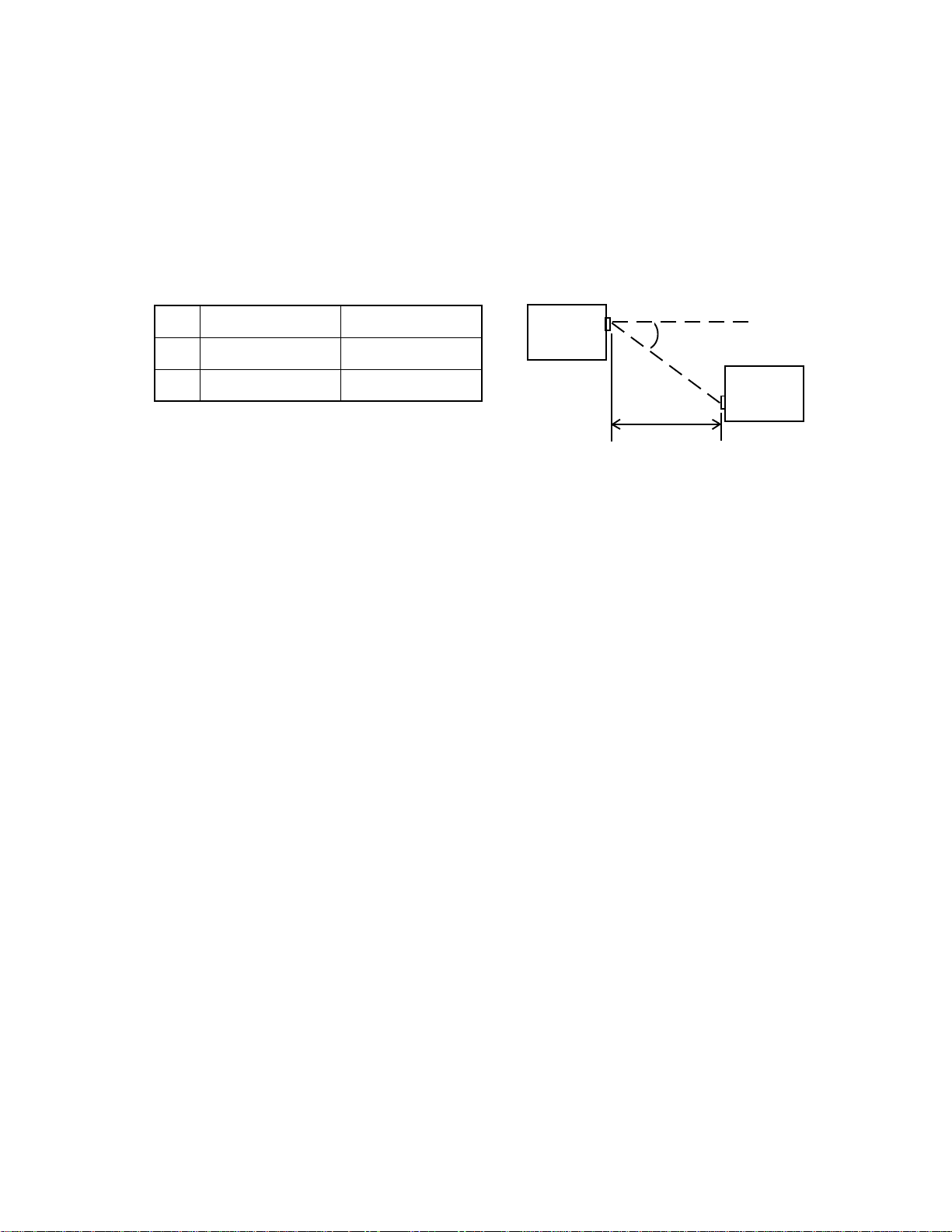
.oN)L(htgneL)A(elgnA
1mc001=L=A±eerged51
2mc5=Leerged0=A
Back-up Battery: OFF: (A-10) 30 ~ 150 µA
(A-11) 50 ~ 250 µA
Voltage Detectors:
VDET1: 2.0 ±0.04 V or under (Low battery message detector for alkaline batteries)
VDET2: 1.6 ±0.04 V or under (Foced power off detector for alkaline batteries)
VDET1R: 2.3 ±0.03 V or under (Low battery message detector for rechargeable battery)
VDET2R: 1.9 ±0.02 V or under (Foced power off detector for rechargeable battery)
VDETS: 2.7 ±0.03 V or under (Low battery message detector for back-up battery)
IrDA:
A
L
A-10/11
A-10/11

— 3 —
UNPACKING
The stylus is inserted into the A-10/A-11 unit.
• A-10/A-11 Unit • Stylus • Dummy Card • RS-232C Cable
The dummy card is inserted in the A-10/A-11 unit.
• CD-ROM (two) • Manuals (Hardware Manual, User’s Guide)
The CD-ROM contains an installer, software applications, and software application documentation.
• AA-size Alkaline Batteries (two)
OPTIONS
UT-S11
This set includes an AC adapter, charger, rechargeable battery pack, and CR-A10.Slip the A-10/A-11 into
the CR-A10 for quick and easy exchange of data with a desktop computer. Also, the CR-A10 makes it
possible to use the RS-232C cable and the Charger at the same time.
AC-S10
This set includes an AC Adapter and CR-M10. The CR-M10 makes it possible to use the RS-232C cable
and the AC Adapter at the same time.
AC Adapter Charger Rechargeable Battery Pack CR-A10
AC Adapter CR-M10

— 4 —
Data Communication Cable SB-62
This cable is used to connect a digital camera or other external
equipment to the A-10/A-11.
CR-A10 CR-M10
CH-50150A NH-10A
Charger Rechargeable Battery Pack

— 5 —
Open: Pressing the latch causes the two
panels to separate slightly, so you can
open them up further by hand.
Close: Press the two panels together until
the latch locks with a click.
To remove: Pull on the part of the stylus
that protrudes from the unit.
To replace: Taking care to orient the stylus
correctly, press it until it clicks into place.
ON OFF
GENERAL GUIDE
• Keyboard
• Power switch
Press to turn power
on and off.
• Touch screen
Displays text data and operational indicators, as well
as on-screen keys and icons that can be operated
using the stylus.
• Reset button
• Backlight button
Press to turn the backlight on and
off. The Backlight turns off auto-
matically if you do not perform any
key or stylus input operation for
some time.
• Data communication jack
For connection of a digital cam-
era or other external equip-
ment.
• Card slot (PC card)
• Stylus
For performing operations on the touch screen.
Take care to avoid damaging or losing the stylus.
• Panel latch
Press to open the panels.
• Main battery holder
Holds main power supply batteries.
• Battery holder release
Slide to release the battery holder when re-
moving it from the A-10/A-11. Both buttons
must be returned to the “NORMAL OPERA-
TION” position for the unit to operate nor-
mally.
• Back-up battery compartment
Holds back-up battery.
• Card lock
Locks a card in the card slot. Unlock
the card when removing it.
• Card eject switch
Slide to eject a card from the
card slot.

— 6 —
• Flashing light
Lights when an alarm time is reached
and to indicate other application-spe-
cific conditions.
• Speaker
Outputs alarm tones and other sounds.
• Notification Button
Turns off the flashing light and stops
the alarm.
• RS-232C/Power connector
For connection of an RS-232C cable,
docking station, mini dock or battery pack
charger.
• Infrared port
• Contrast dial
Rotate to adjust diplay
contrast. Rotate upwards
to make the display lighter
or downwards to make it
darker.

— 7 —
DESKTOP COMPUTER SYSTEM CONFIGURATION
You should check to make sure that the configuration of your desktop computer is as described below to
support the installer and the software applications contained on the CD-ROM.
Minimum Requirements:
Desktop computer with a 486/33DX or higher processor (Pentium P90 recommended)
Microsoft Windows 95 (U.S. Version) or later operating system (will not run on earlier versions of Win-
dows or Windows NT)
8MB of memory (12MB recommended)
10 - 20 MB of available hard disk space (actual requirements will vary based on features you choose to
install and current system configuration)
Available 9 or 25 pin Communications Port (adapter required for 25 pin communication port)
One CD-ROM drive (3.5" high-density disks provided on request)*
VGA or higher resolution graphics card (SVGA 256-color recommended)
Microsoft Mouse or compatible pointing device
Options:
Audio card/speakers for sound
SETTING UP
Use the following procedure to set up the A-10/A-11 before using it for the first time.
1. Load batteries.
Load the two alkaline batteries that come with the A-10/A-11 into its main battery holder.
After loading the main batteries, pull the insulating tape out from under the back-up battery compartment
cover.
2. Turn on power.
Press the power switch to turn on power.
3. Set up the A-10/A-11.
The welcome wizard appears on the screen after the reset routine is complete. Perform the following
procedures in accordance with the guidance messages that appear on the screen.
Touch screen calibration
Time and date setting
Personal data input
Other settings
Altri manuali per Cassiopeia A-10
2
Questo manuale è adatto per i seguenti modelli
3
Indice
Altri manuali Casio Scrivania

Casio
Casio FX-795P Manuale utente

Casio
Casio FX-795P Manuale utente

Casio
Casio PB-1000 Manuale utente

Casio
Casio PB-2000C Manuale utente

Casio
Casio PB-2000C Manuale utente

Casio
Casio FX-890P Manuale utente

Casio
Casio Cassiopeia A-20 Manuale utente

Casio
Casio PB-2000C Manuale utente

Casio
Casio PB-100 Manuale utente

Casio
Casio FX-730P Manuale utente


