CCS WattNode Pulse Output Manuale utente

WATTNODE
®
Pulse Output
Installation and Operation Manual
Continental Control Systems
http://www.ccontrolsys.com
Rev 1.20eUL

Information in this document is subject to change without notice. No part of this document may be
reproduced or transmitted in any form or by any means, electronic or mechanical without the prior written
permission of Continental Control Systems, LLC.
©2007 Continental Control Systems, LLC. All rights reserved.
Printed in the United States of America.
Document Number: WNP-UL-1.20
Revision Date: March 5, 2007
Continental Control Systems, LLC.
3131 Indian Rd., Suite A
Boulder, CO 80301
(303) 444-7422
FAX: (303) 444-2903
Web: http://www.ccontrolsys.com
WattNode is a registered trademark of Continental Control Systems, LLC.
FCC INFORMATION
This equipment has been tested and found to comply with the limits for a Class A digital device, pursuant
to part 15 of the FCC Rules. These limits are designed to provide reasonable protection against harmful
interference when the equipment is operated in a commercial environment. This equipment generates, uses,
and can radiate radio frequency energy and, if not installed and used in accordance with the instruction
manual, may cause harmful interference to radio communications. Operation of this equipment in a
residential area can cause harmful interference in which case the user will be required to correct the
interference at his own expense.

Contents 1
Contents
OVERVIEW................................................................................................................. 2
WattNode .................................................................................................................................................... 2
Current Transformers.................................................................................................................................. 2
Optoisolator Output .................................................................................................................................... 2
INSTALLATION.......................................................................................................... 2
Precautions.................................................................................................................................................. 3
Measurement Configurations...................................................................................................................... 3
Single-Phase Two-Wire ....................................................................................................................... 4
Single-Phase Three-Wire ..................................................................................................................... 5
Three-Phase Four-Wire Wye................................................................................................................ 6
Three-Phase Three-Wire Delta............................................................................................................. 7
Mounting..................................................................................................................................................... 8
Current Transformers.................................................................................................................................. 9
Approved Current Transformers .......................................................................................................... 9
Connecting Current Transformers........................................................................................................ 9
Connecting Voltage Terminals ................................................................................................................. 10
Connecting Output.................................................................................................................................... 11
Installation Summary ................................................................................................................................ 12
Installation Troubleshooting ..................................................................................................................... 13
OPERATING INSTRUCTIONS................................................................................. 15
Power and Energy Computation ............................................................................................................... 15
Scale Factors ............................................................................................................................................. 16
Specifications............................................................................................................................................ 16
Models................................................................................................................................................ 16
Current Transformers ......................................................................................................................... 16
Accuracy............................................................................................................................................. 17
Electrical............................................................................................................................................. 17
Environmental .................................................................................................................................... 17
Mechanical ......................................................................................................................................... 17
WARRANTY............................................................................................................. 18

2Overview
Overview
WattNode
Congratulations on your purchase of the WattNode®, the most compact instrumentation-grade watt/watt-
hour transducer available. Using state-of-the-art ASIC and surface mount components, the WattNode offers
precision energy and power measurements in a compact package. The WattNode enables you to make
precise power and energy measurements from within existing electric service panels avoiding the costly
installation of subpanels and associated wiring. The WattNode is designed for use in demand side
management (DSM), sub-metering, and energy monitoring applications where accuracy at reasonable cost
is essential. The WattNode outputs a stream of pulses whose frequency is proportional to the instantaneous
power and whose count is proportional to total watt-hours. Models are available for single-phase, three-
phase wye and three-phase delta configurations for voltages from 120 VAC to 600 VAC at 50 to 60 Hz.
Current Transformers
The WattNode uses either toroidal or split-core (opening) current transformers (CTs). The WattNode
requires CTs with burden resistors generating 0 – 0.333 VAC. Split-core CTs offer greater ease of
installation, because they can be installed without disconnecting the circuit being measured (although
connecting the voltage terminals on the WattNode requires that at least one circuit in the service panel be
turned off). Toroidal CTs are more compact, more accurate and less expensive, but installation requires
that the measured circuit be disconnected.
The rated current of the CTs should normally be chosen at or above the maximum current of the circuit
being measured. However, if the circuit will normally operate at some fraction of the maximum current and
greatest accuracy is desired at the normal operating power levels, then a CT rated somewhat above the
normal operating current may be a better choice. Take care that the maximum allowable current for the CT
can not be exceeded without tripping a circuit breaker or fuse (see Table 4: Scale Factors) WattNode can
measure up to 150% of rated maximum power for the chosen voltage range and CT, but accuracy will
suffer as the CT’s core begins to saturate. CTs are also nonlinear at very low power levels and may report
less than the true current.
CTs can measure lower currents than they were designed for by passing the wire through the CT more than
once. For example, to measure currents up to 1 amp with a 5 amp CT, pass the wire through the CT once,
then loop back around the outside of the CT, and pass the wire through the CT again. Repeat until the wire
passes through the CT 5 times. The CT is now effectively a 1 amp CT instead of a 5 amp CT. In general,
the current rating of the CT is divided by the number of times that the wire passes through the CT.
Optoisolator Output
The pulse output of the WattNode passes through an optoisolator to provide 2500 volts of isolation. This
allows the WattNode to be interfaced to monitoring or data logging hardware without concern about
interference, ground loops, shock hazard, etc.
The standard output frequency WattNodes (2.667Hz and 4.000Hz) produce a square-wave output with a
duty cycle very close to 50%. The higher output frequency models generate a less regular output
waveform, since variations in the measured power during a single cycle appear in the output. The medium
output frequency WattNodes (193.3Hz and 290.0 Hz) produce a varying square-wave with random
fluctuations from 25% to 75% duty cycle. The highest output frequency WattNodes (773.3Hz and 1160Hz)
produces a waveform with narrow pulses and varying pulse spacing.Installation

Overview 3
Precautions
Only qualified personnel or electricians should install the WattNode. Different versions of the WattNode
measure circuits with voltages from 120 VAC single-phase to 600 VAC three-phase. These voltages are
lethal! Always adhere to the following checklist:
1) CCS recommends that a licensed electrician install the WattNode.
2) CCS recommends that the WattNode be installed either in an electrical enclosure (panel or
junction box) or in a limited access electrical room.
3) Verify that circuit voltages and currents are within the proper range for the WattNode model.
4) Ensure that the line voltage inputs to the WattNode have either fuses or circuit breakers on each
voltage phase (not needed for the neutral wire).
5) Do not install live voltage wires into screw terminals.
6) Always connect the CTs to the WattNode before connecting the line voltages to the WattNode.
Note: in delta configurations the CT screw terminals will be at line voltage when the WattNode is
powered.
7) Do not place more than one voltage wire in a screw terminal.
8) Remember that the screw terminals are not insulated. Do not contact metal tools to the screw
terminals if the circuit is live!
9) Before turning on power to the WattNode, ensure that all the wires are securely installed by
tugging on each wire.
10) Do not install the WattNode in an environment where it may be exposed to temperatures below -
30°C or above 60°C, excessive moisture, dust or other contamination.
Measurement Configurations
Below is a list of different power measurement configurations, with connections and recommended
WattNode models. Note: Ground wires do not carry current except in the case of a malfunction of the
circuit being measured and are not used by the WattNode.
DANGER — HIGH VOLTAGE HAZARD
WARNING - THESE INSTALLATION/SERVICING INSTRUCTIONS ARE FOR USE
BY QUALIFIED PERSONNEL ONLY. TO AVOID ELECTRICAL SHOCK, DO NOT
PERFORM ANY SERVICING OTHER THAN THAT CONTAINED IN THE
OPERATING INSTRUCTIONS UNLESS YOU ARE QUALIFIED TO DO SO.
4Overview
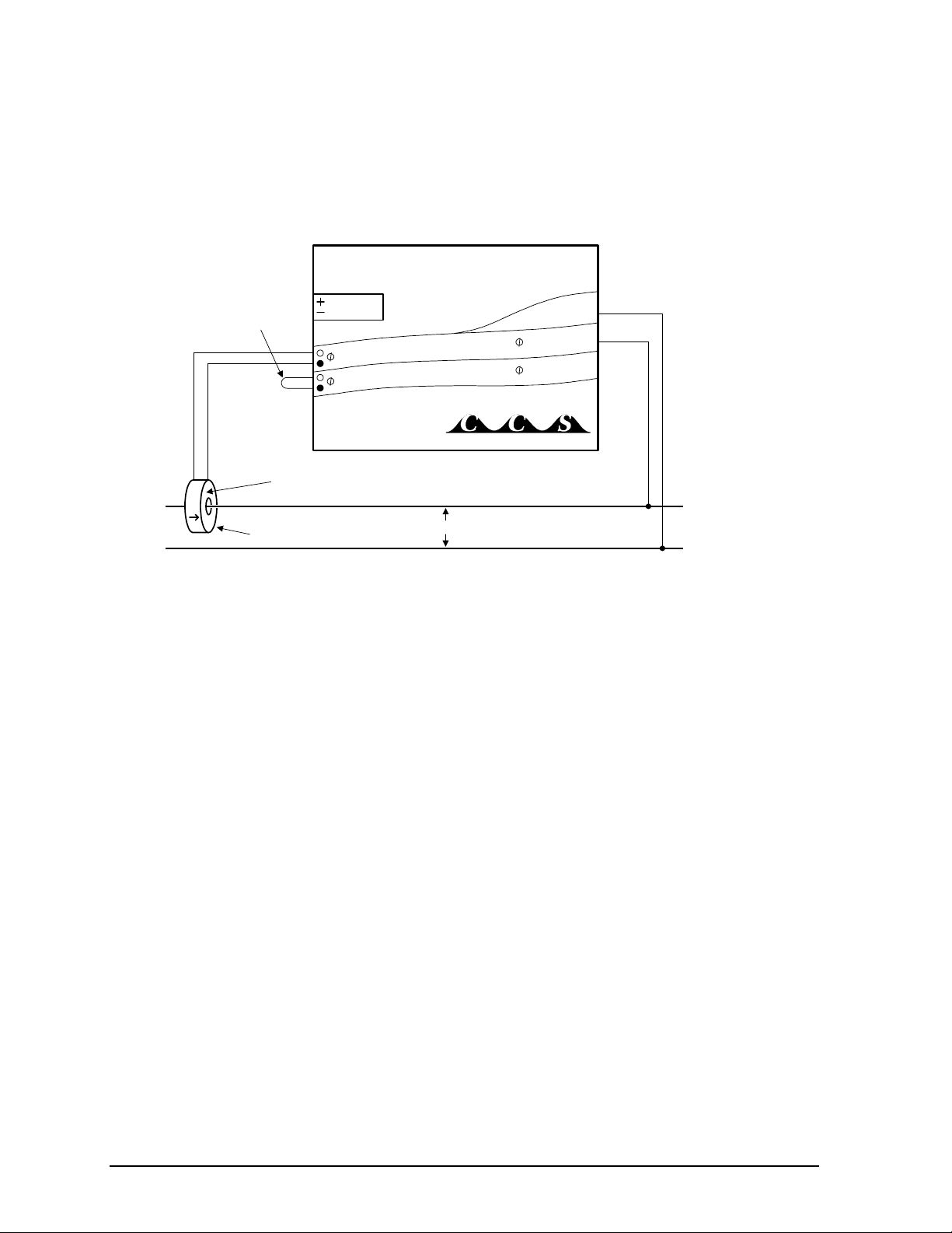
Single-Phase Two-Wire
The single-phase two-wire 120 VAC configuration is most often seen in homes and offices. The two wires
are neutral and line. Any unused CT inputs must be shorted with an insulated jumper wire. Single-phase
two-wire circuits should be measured with models WNA-1P-240-P or WNA-3Y-208-P. If you wish to
measure a single phase two wire 220 to 240 VAC circuit, use the WNA-3Y-400-P and connect the two
wires to the neutral and phase A terminals.
Phase A
LINE
Neutral
LOAD
Current
Transformer
WHITE
BLACK
Source
Face
120 VAC
Neutral
WNA-1P-240-P
Continental Control Systems
W
ATT
N
ODE
B CT
A CT B 120 VAC
A 120 VAC
BLACK
WHITE
Shorting
Wire
Output
Figure 1: One-Phase Two-Wire Connection
Overview 5
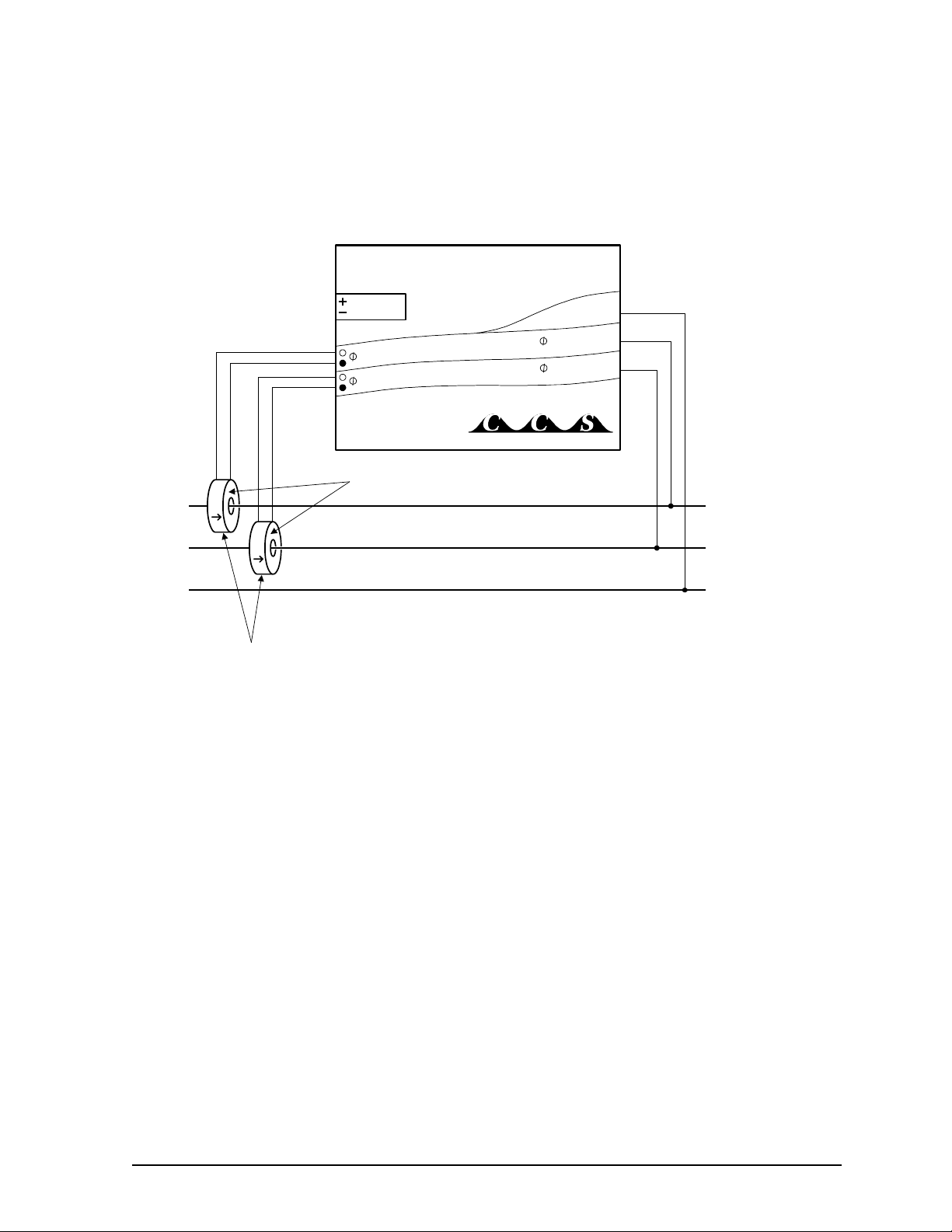
Single-Phase Three-Wire
This is seen in residential and commercial service with 240 VAC for large appliances. The three wires are
neutral and two line voltage wires with AC waveforms 180° out of phase. This results in 120 VAC
between either line wire and neutral, and 240 VAC (or sometimes 208 VAC) between the two line wires.
Any unused CT inputs must be shorted with an insulated jumper wire. Single-phase three-wire circuits
should be measured with models WNA-1P-240-P or WNA-3Y-208-P.
Neutral
Phase A
LINE
Phase B
LOAD
Current
Transformers
WHITE
BLACK
Source
Faces
WHITE
BLACK
Neutral
Output
WNA-1P-240-P
Continental Control Systems
W
ATT
N
ODE
B CT
A CT B 120 VAC
A 120 VAC
Figure 2: One-Phase Three-Wire Connection
6Overview
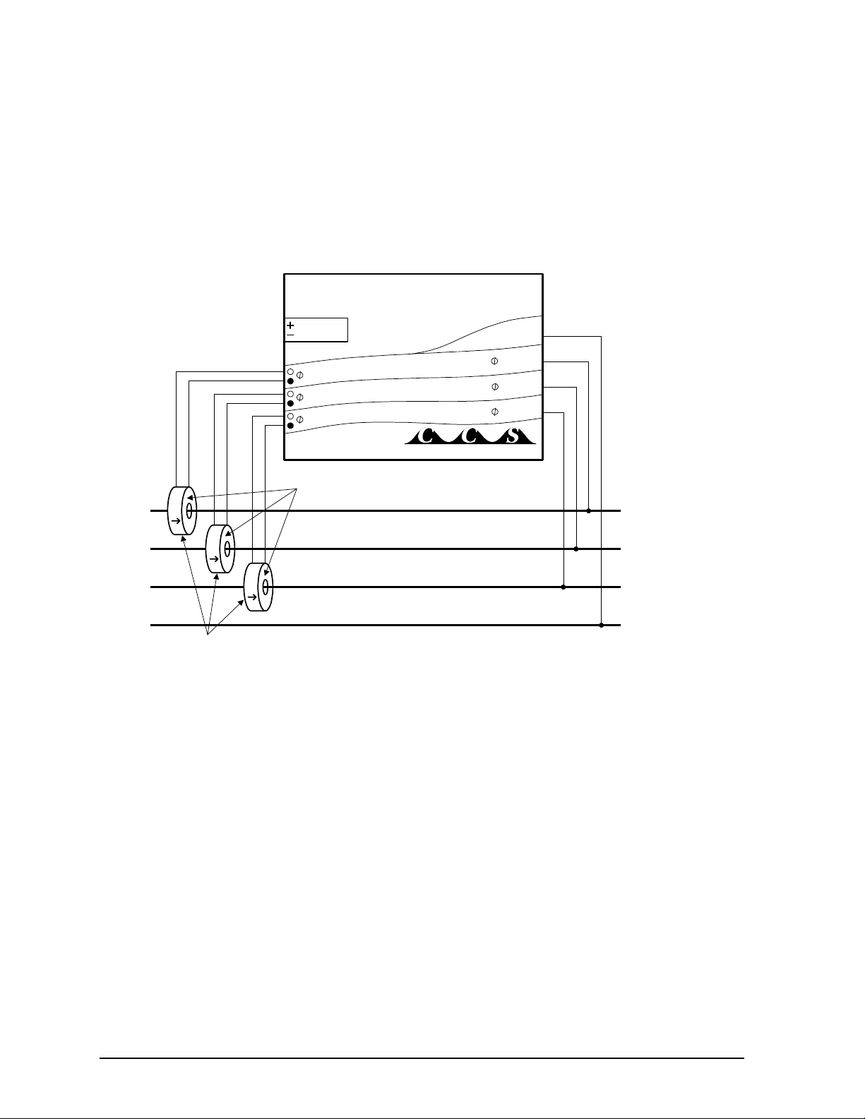
Three-Phase Four-Wire Wye
This is typically seen in commercial and industrial environments. The wires are neutral and three power
lines with AC waveforms shifted 120° between the successive phases. With this configuration, the line
voltage wires may be connected to the phase A, B and C terminals in any order, so long as the CTs are
connected to matching phases. It is important, however, that you connect the neutral line correctly.
Three-phase four-wire wye circuits should be measured with the WNA-3Y-208-P (208 VAC phase to
phase and 120 VAC phase to neutral), the WNA-3Y-400-P (400 VAC phase to phase and 230 VAC phase
to neutral), the WNA-3Y-480-P (480 VAC phase to phase and 277 VAC phase to neutral), or the
WNA-3Y-600-P (600 VAC phase to phase and 347 VAC phase to neutral), depending on the line voltage.
Neutral
Phase A
LINE
Phase B
Phase C
LOAD
Current
Transformers
WHITE
BLACK
Source
Faces
WHITE
BLACK
WHITE
BLACK
Neutral
Output
WNA-3Y-xxx-P
Continental Control Systems
W
ATT
N
ODE
C CT
B CT
A CT
C VAC
B VAC
A VAC
Figure 3: Three-Phase Four-Wire Wye Connection
Overview 7
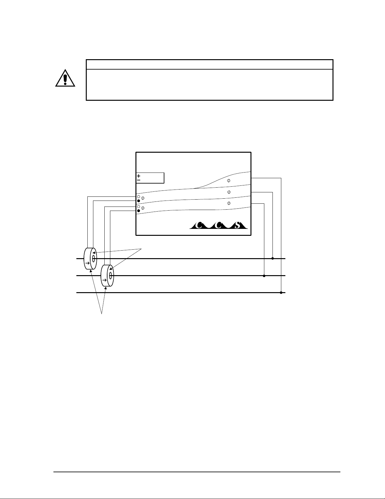
Three-Phase Three-Wire Delta
This is typically seen in manufacturing and industrial environments. There is no neutral wire, just three
power lines with AC waveforms shifted 120° between the successive phases. With this configuration, the
line voltage wires may be connected to the phase A, B and C terminals in any order, so long as the CTs are
connected to matching phases. Three-phase three-wire delta circuits should be measured with the
WNA-3D-240-P or the WNA-3D-480-P.
Phase B
LINE
Phase C
Phase A
LOAD
Current
Transformers
WHITE
BLACK
Source
Faces
WHITE
BLACK
Output
WNA-3D-xxx-P
Continental Control Systems
W
ATT
N
ODE
C CT
B CT C VAC
B VAC
A VAC
Figure 4: Three-Phase Three-Wire Delta Connection
WARNING
This configuration is dangerous because there is no neutral wire, and as a result the screw
terminals to connect the CTs will have line voltages on them whenever the WattNode is
powered. Therefore, for safety, it is critical that the WattNode is not powered while
connecting the CTs.
8Overview
Mounting
Mount the WattNode so that it is protected from moisture, direct sunlight and high temperatures. Due to its
exposed screw terminals, the WattNode should always be installed in an electrical service panel, a junction
box, or an electrical closet. The WattNode may be installed in any position.
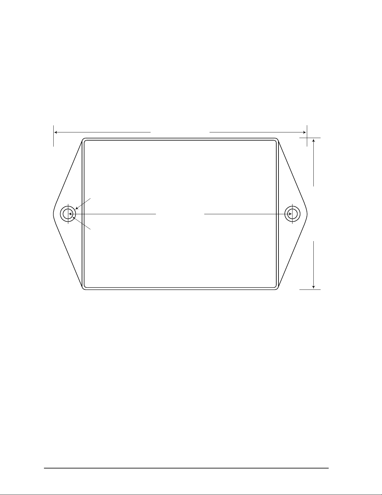
The WattNode has two 7/32" (5.5 mm) mounting holes spaced 5" (127 mm) apart (center to center). These
mounting holes are normally obscured by the detachable screw terminals. Remove the screw terminals by
pulling outward while rocking from end to end. The WattNode or Figure 5 may be used as a template to
mark mounting hole positions, but do not drill the holes with the WattNode in the mounting position
because the drill bit or chuck may damage the plastic WattNode housing or connectors.
127 mm (5.0")
143.5 mm (5.65")
85.5 mm (3.37")
32.5 mm (1.28") High
Ø 9mm (11/32")
Ø 5.5mm (7/32")
Drawn to Scale
Figure 5: WattNode Dimensions
To protect the WattNode’s plastic case, use washers if the mounting screws could pull through the
mounting hole or damage the case. Also, take care not to over-tighten the mounting screws, as long term
stress on the case may cause cracking.
Questo manuale è adatto per i seguenti modelli
7
Indice
Altri manuali CCS Trasduttore


Manuali Trasduttore popolari di altre marche


Mianyang Weibo Electronic
Mianyang Weibo Electronic WB Series Manuale utente

ProMinent
ProMinent Dulcometer DMT Manuale utente

MKS
MKS MicroPirani 925 Series Come usare

WIKA
WIKA WU-20 Manuale utente

Alcatel Vacuum Technology
Alcatel Vacuum Technology BARATRON 622A Manuale utente

Camille Bauer
Camille Bauer SIRAX CH-5610 Manuale utente


