CCTV JE900BN Manuale utente

User’s Manual for Smart Constant Speed Dome Camera
Please read the manual carefully before installing and using the unit.
Model: JE900BN, JE900BNC

1
Table of Contents
PART I: INTRODUCTION................................................................................................................................ 2
1-1 INSTRUCTIONS:........................................................................2
1-2 CHARACTERISTICS...................................................................2
1-3 MAIN TECHNICAL DATA...........................................................3
1. Electric Index ...................................................................................................................................... 3
2. Mechanical Index ............................................................................................................................... 3
3. Ambient Index..................................................................................................................................... 3
4. Camera Index ..................................................................................................................................... 4
1-4 STYLES OF INSTALLATION AND ANCILLARY COMPONENTS .........4
PART II: INSTALLATION PROCEDURES ..................................................................................................... 4
2-1 OUTER SHAPE AND INSTALLATION SIZE .....................................4
2-2 INSTALLATION OF CAMERA BLOCK ...........................................5
2-3 CONNECTION OF THE CAMERA AND THE HOUSING.....................6
2-4 INSTALLATION OF DOME COVER...............................................8
2-5 HOUSING AND WALL-MOUNT BRACKET INSTALLATION ............9
2-6 INSTALLATION OF THE BRACKET ............................................10
2-7 POWER SUPPLY ADAPTER INSTALLATION ................................. 11
2-8 INSTALLATION FOR EMBEDDED DOME CAMERA ......................12
2-9 CONNECTING POWER AND SIGNAL CABLE .............................. 12
PART III: SETUP AND OPERATE.................................................................................................................. 14
3-1 PROTOCOL, BAUD RATE, ADDRESS AND SPEED SETUP .............14
3-2 RUNNING STATE TEST WHILE THE CAMERA POWER ON .............16
3-3 THE PARTICULAR COMMAND AND ITS DEFINITION ...................17
3-4 SET UP AND PREVIEW PRESET POSITIONS ................................17
3-5 SETUP AND RUNNING OF TOUR GROUP ....................................19
3-6 SETUP AND SCAN BETWEEN TWO POINTS .................................20
3.6.1 Setup of Left/right Limiting Positions....................................................................................... 20
3.6.2 Start scanning between two points ......................................................................................... 21
3-7 START 360° SCANNING FUNCTION OF THE PAN/TILT .................21
3-8 STOP THE AUTO SCANNING .....................................................21
3-9 THE SETUP, ACTIVATING AND EXITING OF DEFAULT POSITION .21
PART IV: APPENDIX...................................................................................................................................... 22
PART V. CONNECTING SKETCH................................................................................................................ 22

2
Part I: Introduction
1-1 Instructions:
We greatly appreciate your choosing our product!
The product is under one year warranty, including free maintenance or spare parts
replacement. Do not dismantle and repair the unit without the company’s authorization.
Damage or breakdown arising from the following circumstances is No free maintenance:
1. dismantling and repairing of the unit without the company’s authorization;
2. the transportation, loading or unloading of the unit which is arranged by the
customer;
3. using and maintenance of the unit without observing the instructions in the
User’s Manual, including damage or breakdown arising from crashing, crushing,
and unit affected with damp, liquids, corrosive or other man-made causes;
4. inapplicable ambient temperature or overloaded operation; surface abrasion or
damage emerging when the unit is being used;
5. natural disasters and other accidents.
Attention: To realize all the functions of the unit, a compatibility test must be carried
out before applying other manufacturer’s spare parts in the system.
1-2 Characteristics
1. Precise conductive slip-ring is adopted, which 360°pan endless running and
all-direction monitoring is realized, and cable-twisting problem with common
constant speed domes are effectively solved.
2. The operation is based on advanced stepper motors and driving circuits, which
ensures smooth running, long time consecutive working, long lifespan and high
reliability.
3. PCB board is very concise, most of the parts on the PCB board are highly
integrated and modulated, thus the malfunction is greatly reduced and the
stability of the performance is ensured.
4. The design of the outer housing is reasonable, elegant and practical. It can
endure long-term operation without distortion. And the installation is fast and
convenient.
5. The function of Position Limiting is realized with photoelectrical sensors, which
avoids traditional disadvantage of mechanical and switch Position Limiting (the
switch lifespan is 200,000 times ON/OFF).
6. Left/right limiting positions can be set up by the key of the camera panel, it also
can be set up through our company’s keyboard, which avoids the limitations that
it can only be set up from the front terminals.
7. There are 4 levels of running speed optional for the unit: 6°, 9°, 12°,15°/S, which

3
can be adjusted according to actual conditions.
8. The built-in PCB panel supports multi mainstream protocols, which can be input
according to the customer’s needs. The Baud rate is also adjustable.
9. The unit adopts DC14V(15V) power supply and separates from it the components
that produce heat in the process of transformation, which prolongs the durability
of the unit. The unit is anti-jamming and anti-crashing.
10. Two grades anti-lightening technology, which effectively improve the
anti-lightening and anti-interruption ability
11. If the power is off when the unit is scanning or cruising, it will automatically
resume scanning or cruising once power supply is on.
12. Support 16 preset positions, 1 tour, left & right scan, 360° scan.
13. The unit has one guard position; the user can preset it for a key monitor area
according to the actual conditions. If not operated after 5 minutes, it will
automatically monitor the preset position.
1-3 Main Technical Data
1. Electric Index
Power supply DC14V---15V 2A
Dome motor DC14V---15V/0.5A
Camera lens motor DC12V/100mA
Camera power supply 12V/1A
The working range of heater
and fan Fan(≥50°C); heater (≤5°C)
Addresses range 1~63
Communication system RS485 bus controlling
Communication protocol Pelco-D, Pelco-P, Pelco-D1
Baud rate 1200bps, 2400bps, 4800bps, 9600bps
Controlling device video matrix, DVR controlling keyboard
Preset position quantity 16 preset positions
Auto Scan Scan between two points and 360° endless scan
Tour group quantity 1 group(16 preset positions can be included)
Default position function Yes
2. Mechanical Index
Dome movement pan 360° endless, tilt 0°-90°
Dome speed 6º/S, 9º/S, 12º/S, 15º/S adjustable
Movement limiting position pan adjustable within the dome movement
scope
3. Ambient Index
Ambient temperature 0ºC~49ºC (without temperature controlling devices)
-40ºC~60ºC (with temperature controlling devices)
Relative Humidity ≤95%RH

4
4. Camera Index
Image Sensor 1/4〞Super Had CCD
Resolution. 480TV Line
Lens f=3.25-88mm High Durability 27X Zoom Lens
Angle of View 48 degrees (w) Horizontal 3 degrees (t)
Sync System Internal/Line Lock NTSC 60 Hz , PAL 50HzC
Minimum illumination 0.5Lux/0.1Lux with B/W mode
IR Sensitive 0Lux with IR on
Video Focus Auto/Manual (Near-Far)
White Balance Auto/OFF
BLC Auto/OFF
Electric shutter 1/50~1/12000s
S/N Ratio >50dB
Video Output Composite 1.0+/-0.2Vp-p
1-4 Styles of Installation and Ancillary Components
Item installation Bracket Heater & fan
Wall installation Arm bracket
7’, 9” Outdoor Ceiling installation Pole mounting 20cm or 40cm Yes
Yes
7”, 9” Indoor Ceiling Embedded
No bracket;
Steel wire rope to be prepared by
the user
Table 1: Styles of Installation and Ancillary Components
Part II: Installation Procedures
2-1 Outer shape and installation size
1. Dimension for outdoor Dome Camera

5
2. Dimensions for embedded Dome Camera
2-2 Installation of Camera block
1. Firstly make sure the size of the selected video camera is within the acceptable
range
Then follow the direction indicated on the camera suspender, and fix the camera to it
with special screws. Make the length in the front and the back of the camera equal

6
(D1=D2). (Refer to the figure below.) Observe if there is any collision or friction between
the camera and the vitreous cover. If there is any, adjust the camera.
2. Connect Lens Controlling Cable
Camera Lens Controlling Cable should be provided by the camera supporter.
Connect the camera controlling cable well according to the corresponding relationship
between the camera and the outlet of PCB panel shown in the following table.
Controlling signal of the camera lens Corresponding outlet on PCB panel
Camera power supply +12VDC, GND
Lens Zoom ZOOM
Lens Focus FOCUS
Lens Iris IRIS
Lens Controlling public ground COM
3. Connect Video Cable
Connect BNC video outlet with the video output outlet of the camera, then use the
binding wire to tie the video cable inside the camera and the lens cable into the hole
beside the lens connecting outlet on the PCB panel. After installing the camera, please
set up communication protocol, Baud rate, address, etc.
2-3 Connection of the Camera and the Housing
Install the well-setup module equipped with camera into the housing. Procedures
shown below:

7
Step 1
Push the connecting ports end of the power, video and controlling integrated cable
through the central hole of the peg-board, and then fix the connecting ports into the
socket on the module. Then fit the parts shown with dotted lines on the module into the
indentation shown with dotted lines on the peg-board. (See the above figure)
Step 2
Hold the module, then turn it to the direction as the arrow sign for about 50 degrees
till it can not move forward any longer, make sure the three installing pegs are in right
positions. (See the above figure)

8
Step 3
After the module is in right position, tighten the special screw (the screw will not drop
even when it is loosed to the end) manually or with a screwdriver. Be sure the screw is
tight, otherwise, the module might fall when the unit is running. Installation of the camera
completed. (See the above figure)
Attention: Once the module is installed well with the housing, please don’t merely pull
the power, video and controlling integrated cable to lift the unit, with which operation the
connecting ports of the integrated cable may be pulled out, or even worse, the
connecting ports may be damaged permanently. The right operation method is: hold the
whole housing in your palms, then continue with the installing and connecting work.
2-4 Installation of Dome Cover
1-5 For outdoor dome camera
Put the dome cover to the housing well in right position, then tighten the two screws
manually or with a screwdriver. (See the above figure)

9
2-5 For embedded dome camera
Fit the three plastic pegs on the dome cover to the corresponding ones on the
housing, then turn it to the right for about 20 degrees till it stops moving. (See the
above figure)
2-5 Housing and Wall-mount Bracket installation
Push the power, video and controlling integrated cable through the bracket hole,
then direct the top of the housing to the bracket hole and tighten them. Use a
screwdriver to drive the three M6 screws on the bracket into the screw slot. (See the
Questo manuale è adatto per i seguenti modelli
1
Indice
Altri manuali CCTV Telecamera di sicurezza

CCTV
CCTV WDR3600 Manuale utente

CCTV
CCTV CMF1171X Manuale utente

CCTV
CCTV MS9110 Manuale utente

CCTV
CCTV CSP-750ADV Manuale utente

CCTV
CCTV PTA1215X Manuale utente

CCTV
CCTV URZ0147 Manuale utente

CCTV
CCTV CSP-PB750 Manuale utente

CCTV
CCTV HCAM675B Manuale utente

CCTV
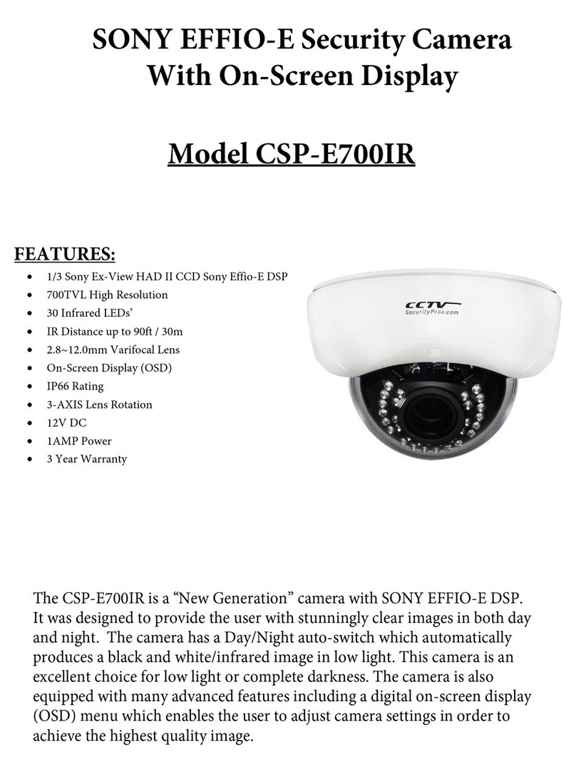
CCTV CSP-E700IR Manuale utente

CCTV
CCTV je 6114 Manuale utente