CDVI 300-LADJ Manuale utente
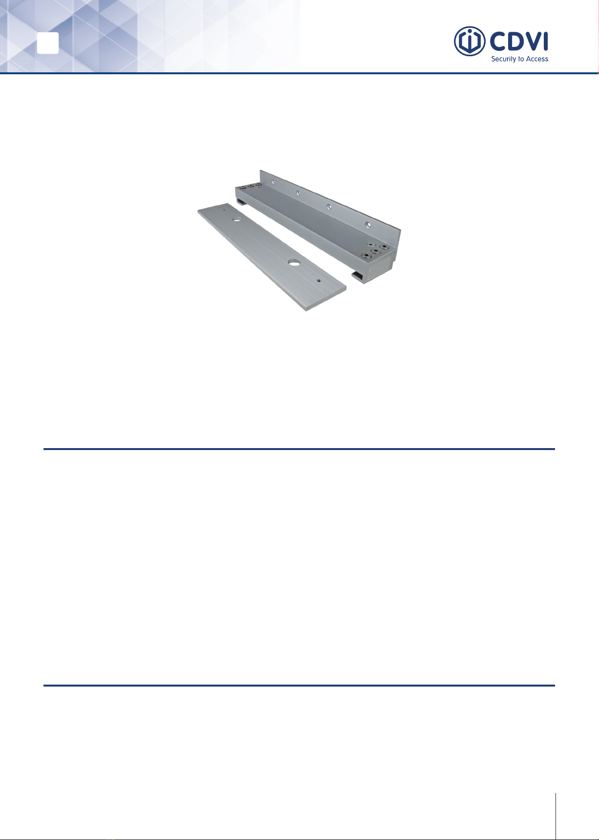
EN EN 300-LADJ
Electromagnetic Lock Bracket
1
Instructions of Use
Quick Start Guide
The bracket comes completely assembled. Mount the bracket, t the mag to the slider
plate, line up with the armature, wire up, power up, tighten up and walk away.
Note: Each 300-LADJ bracket is bespoke to each maglock type and size. Please ensure
you have the correct bracket for the relevant mag lock.
What is this bracket for?
• The 300-LADJ bracket is useful when the maglock cannot directly t under the tran-
som and where you would normally use an “L” bracket.
• This bracket allows innite adjustment and positioning of the maglock. It can then
meet the armature perfectly with minimal effort.
• Depending on the size of the magnet you can slide the plate forward or backward
and even angle it, if that is what is needed.
• There is a cavity and a cut out in the bracket to make cabling easier, without
exposing or pinching the cable.
• It allows you to adjust the position of the magnet easily even after mounting.
Bracket Fitting
The 300-LADJ is easy to t:
1. Fit the main body to the transom and the armature to the door.
2. Secure the magnet to the sliding plate.
3. Slide the plate into the bracket and line it up to the armature plate.
4. Tighten the screws.
EN EN
300-LADJ
Electromagnetic Lock Bracket
2
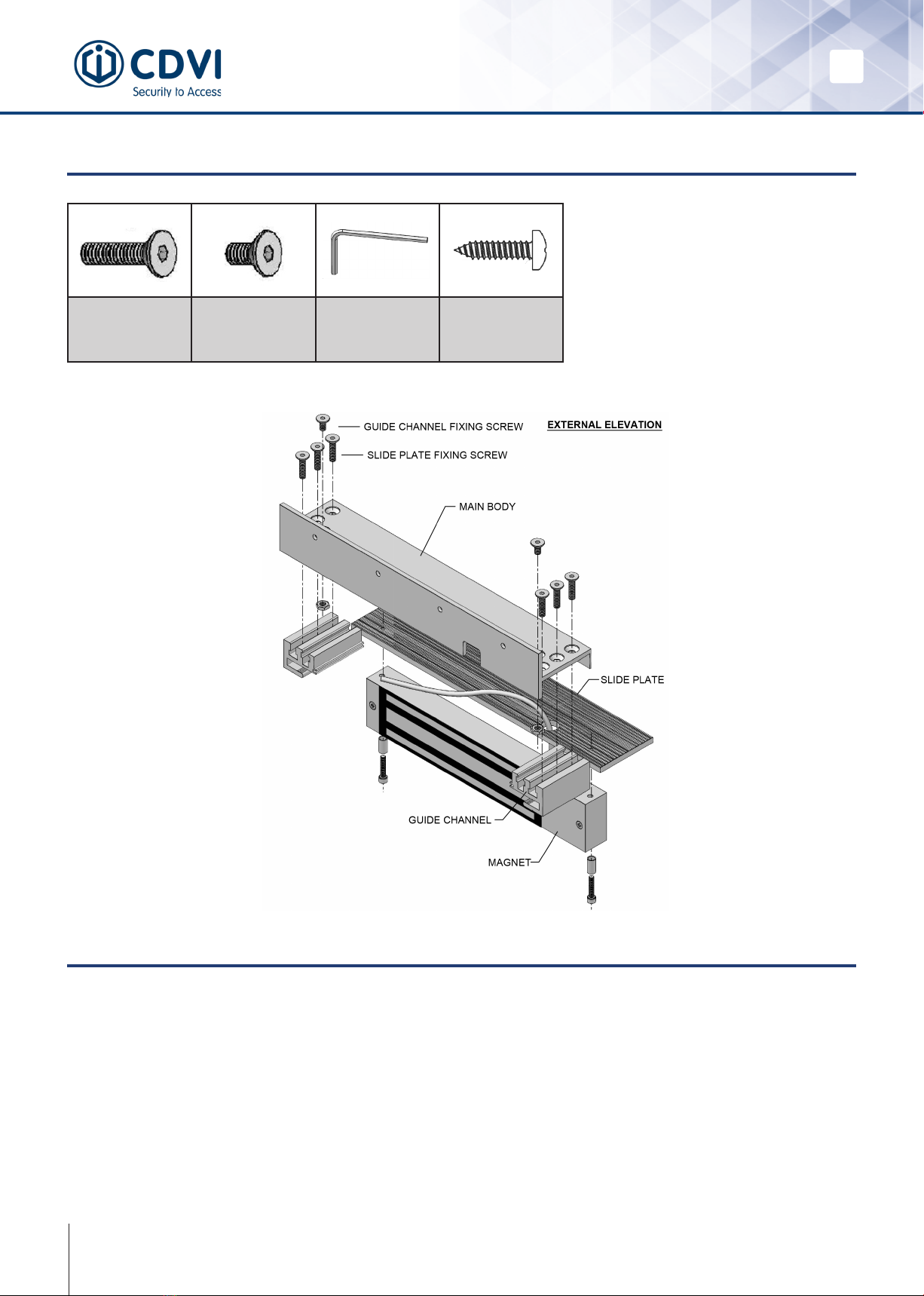
Package Contents & Components
6 x M6x22
for sliding plate
2 x M6x22
for guide
channels to
body
1 x Allen key 4 x self-tapping
transom xings
STEP I
1. Remove the slide plate from the main body - On top of the main body bracket there
are 3 xings at either end. Loosen all three xings, on both sides (do not over
loosen otherwise they will fall out of the xing nuts and will have to be relocated)
just enough for the plate to slide out easily.
2. Remove the xing plate that comes attached to the top of the magnet – note that
not all magnets have this.
Installation
EN EN 300-LADJ
Electromagnetic Lock Bracket
3
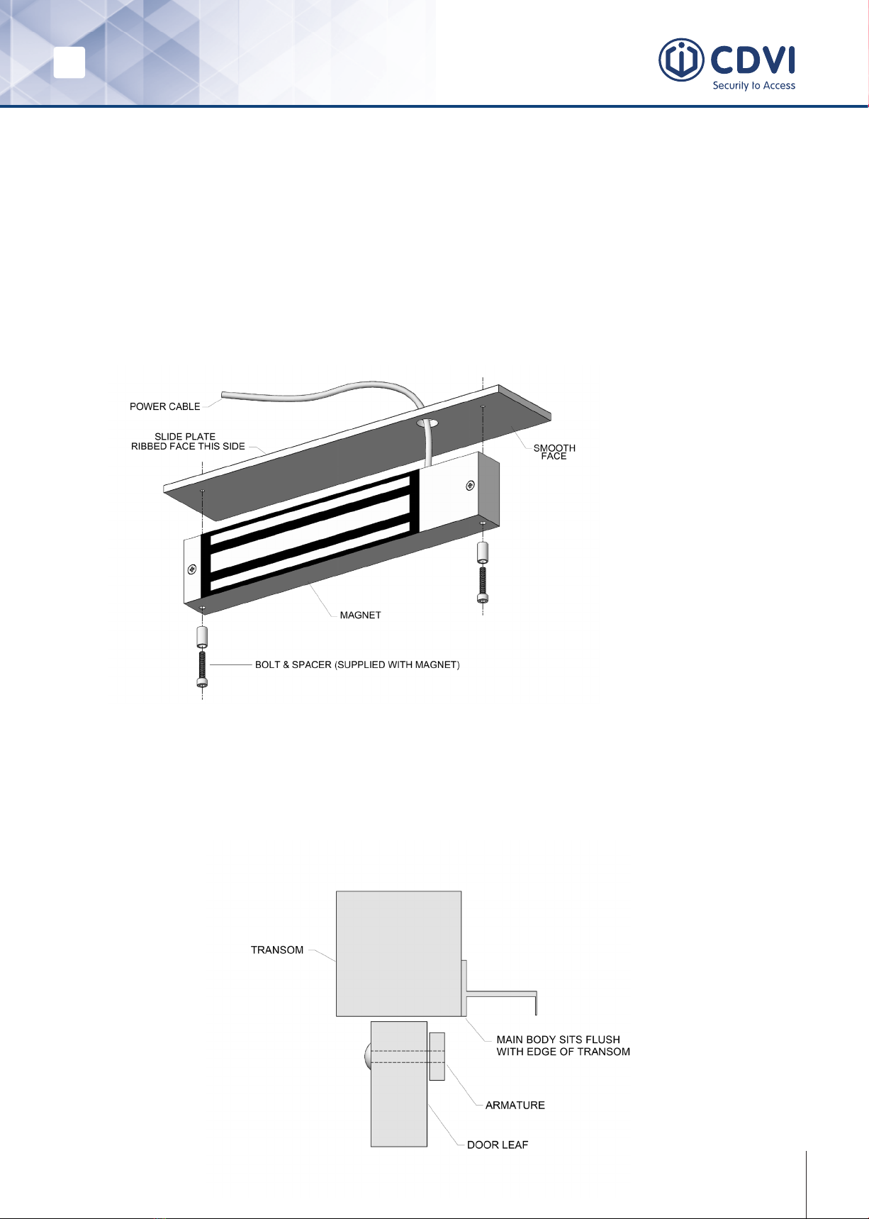
3. Mount the magnet to the at sliding plate in the same way you would for a stand
ard “L” bracket (see diagram below) and secure through the 2 or 4 pre-drilled holes,
depending on the magnet you are using.
4. Ensure the hole where the wire comes out of the magnet corresponds with the one
on the at plate and that the magnet faces outwards on the edge of the slide plate
(see drawing below).
This can all be pre prepared before attending site or in bulk on site before taking to
each door location in order to save time.
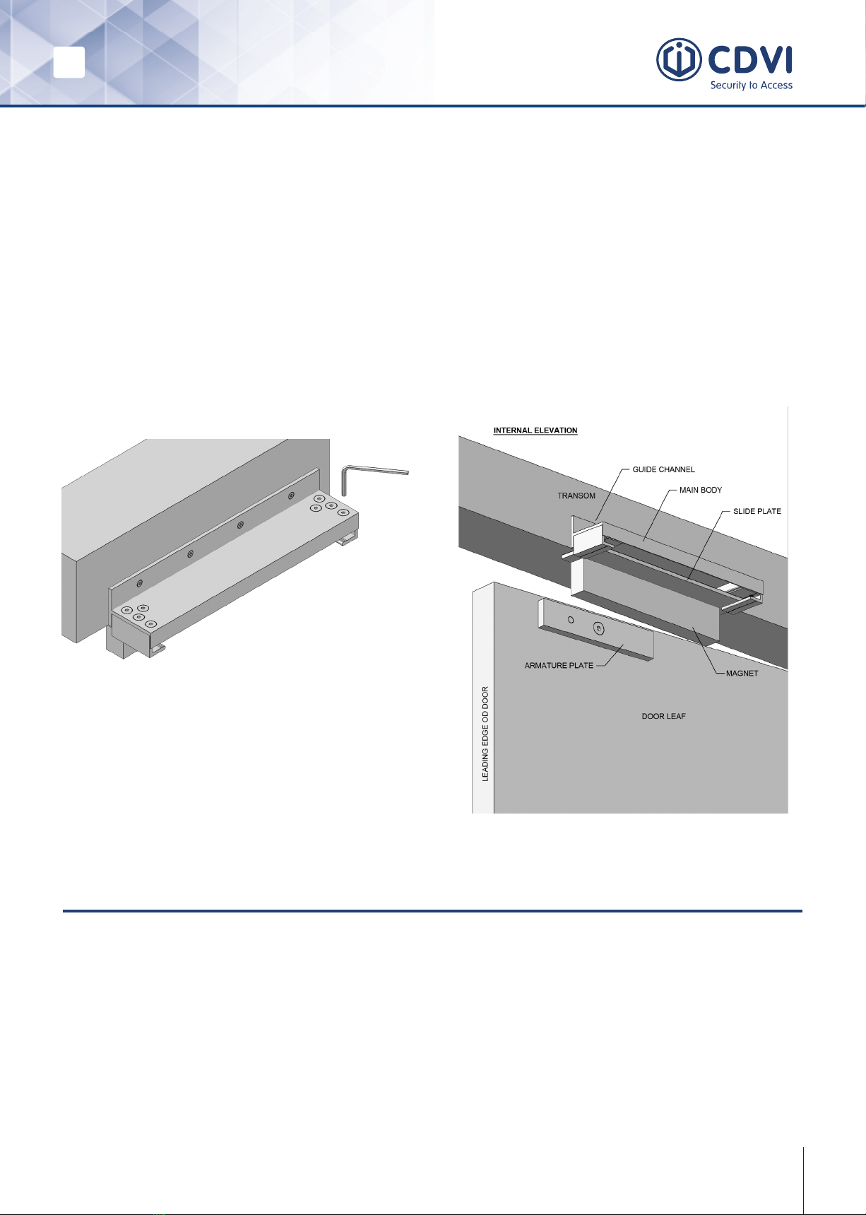
STEP II
Fit the armature to the door and secure the main body to the transom in the same way
you would with an “L” bracket taking care to ensure that the sliding plate can travel
freely under the transom.
Depending on the type of door frame
the mag lock can be tted at the
front or the back of the plate which is
achieved by simply turning the plate
around
EN EN
300-LADJ
Electromagnetic Lock Bracket
4
STEP III
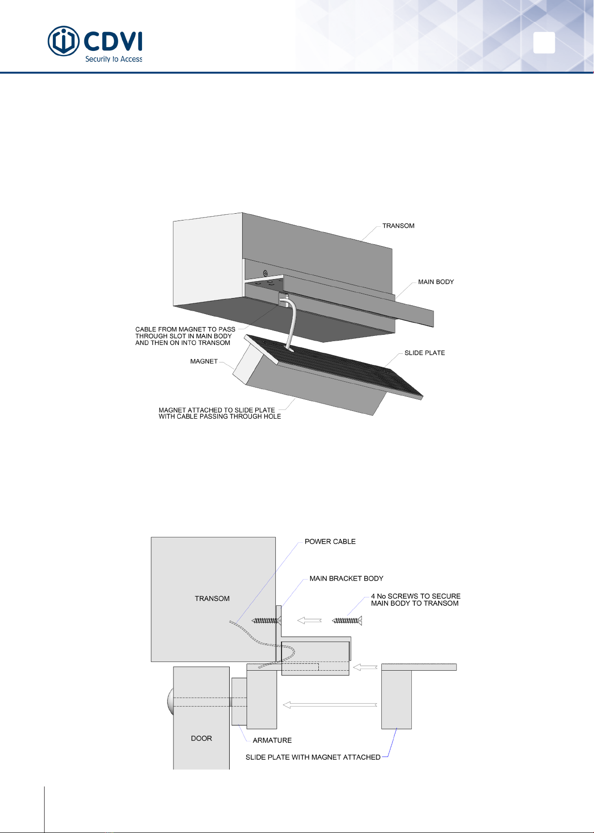
Make a hole in the transom using the cut out at the back of the main body as a guide
in order to make a clean cable route from the magnet through the transom.
Note: There is a void within the main body bracket to prevent any cables being pinched
STEP IV
Slide the plate with the magnet attached into the main body. Position it in the way that
main body and armature are aligned on the door.
EN EN 300-LADJ
Electromagnetic Lock Bracket
5
STEP V
Once the connections have been made, the magnet can be powered up. Slide the plate
(backwards or forwards, depending on the rebate) until it is ush against the armature
(with the door closed).
Note that the slide plate can be angled to accommodate the position of the armature if
the door comes in at an angle.
After aligning the magnet and armature plate and after powering up, use the Allen key
to tighten the M6 screws on both sides.
Note: Ensure to alternate and tighten one screw on each side to have an equal spread
of pressure.
Important Information
• It is essential that the transom you are mounting the bracket on is strong enough to
accommodate the bracket and its xings. If in doubt, please consult the door
supplier.
• Ensure that the supplied xings are not exchanged otherwise this will affect the
performance of the bracket
• It is essential to follow CDVI’s guidelines on how to mount the electromagnetic lock.
• The thread lock must be applied to all xings.
For queries visit our website www.cdvi.co.uk or contact us at
+44 1628 531300
CDVI UK, Unit B1, Knaves Beech Business Centre, Davies Way,
Loudwater, High Wycombe, HP10 9QR
Internal Reference Code: CDVI_300-LADJ_QS_01_EN_A4_C
All the information contained within this document (pictures, drawings, features, specications and dimensions)
could be perceptibly different and can be changed without prior notice.
Indice


