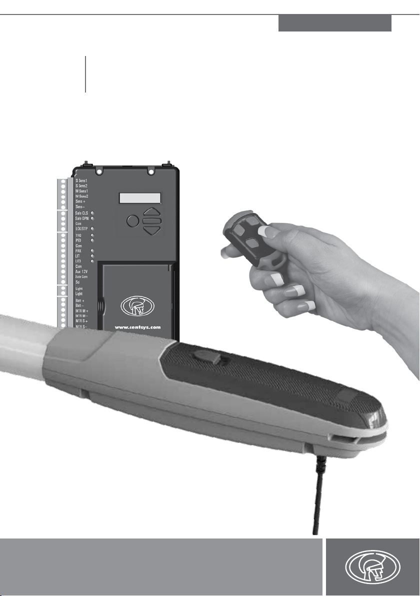
CENTURION SYSTEMS V400 Manuale utente
page 1 www.CentSys.com
Centurion Systems (Pty) Ltd
SWING GATE OPERATOR
V400 & V500
LINEAR SWING GATE OPERATOR
MECHANICAL INSTALLATION MANUAL
After-sales
multi-language
Technical Support
from 07h00 to 18h00
UTC+2
Monday to Friday
Manufacture to
international
quality standard
ISO 9001:2008
100%
testing of
products
In-house
R&D
development
team
Centurion Systems (Pty) Ltd reserves the right to make changes to the products described in this
manual without notice and without obligation of Centurion Systems (Pty) Ltd to notify any persons
of any such revisions or changes. Additionally, Centurion Systems (Pty) Ltd makes no representations
or warranties with respect to this manual. No part of this document may be copied, stored in a retrieval
system or transmitted in any form or by any means electronic, mechanical, optical or photographic,
without the express prior written consent of Centurion Systems (Pty) Ltd.
1986 1990 1995 1999 Today
COMPANY PROFILE
Company Prole
Sales and technical support
to Africa, Europe, Asia,
the Americas, Australia
and the Pacic

www.CentSys.com
SAFETY
FIRST IMPORTANT SAFETY INSTRUCTIONS
1. General Description
2. Icons Used in this Manual
3. Specications
3.1. Physical Dimensions
3.2. Technical Specications
3.3. V-Series Controller
3.4. Lightning Protection
3.5. Power Supply
3.6. Allowable Gate Mass
3.7. Allowable Wind Load
4. Product Identication
4.1. V-Series Wall Box
5. Required Tools and Equipment
6. Preparation of Site
6.1 General Considerations for the Installation
6.2. Determine Gate Opening Angle
6.3. Key Terms Used in this Section
6.4. Side Wall Limitation - Inward Opening
6.5. Pillar Hinge Depth Limitation - Inward Opening
6.6. Wall Bracket Mounting Methods
6.7. Strength of the Gate and Gate Bracket
7. Cabling Requirements
8. Critical Installation Checklist
9. Operator Installation - Inward Opening Gate(s)
10. Operator Installation - Outward Opening Gate(s)
page 5
Contents
CONTENTS
page 8
page 9
page 10
page 10
page 11
page 12
page 12
page 12
page 13
page 14
page 15
page 16
page 17
page 18
page 18
page 19
page 20
page 20
page 21
page 22
page 24
page 25
page 26
page 27
page 36

page 4 www.CentSys.com
STEP
1
These quick steps are for the experienced installer who needs a checklist to get a
standard installation up and running in the minimum of time.
Detailed installation features and functions are referred to later in this manual.
Gather Required Tools and Equipment
STEP
2
STEP
3
Heed Necessary Site Considerations
Check Cabling Requirements
STEP
4Determine Gate Swing Angle
STEP
5
STEP
6
STEP
7
STEP
8
STEP
9
Conrm that gate leaf meets allowable wind loading specications
Determine Installation Type
• Inward Opening Installation
• Outward Opening Installation
Mount the Gate and Wall Bracket(s)
Install Operator and Link to Gate
Mount Controller Enclosure
FAST TRACK Mechanical Setup
MECHANICAL SETUP

page 5www.CentSys.com
ATTENTION
To ensure the safety of people and possessions, it is important that you
read all the following instructions.
Incorrect installation or incorrect use of the product could cause
serious harm to people.
The installer, being either professional or DIY, is the last person
on the site who can ensure that the operator is safely installed, and that
the whole system can be operated safely.
IMPORTANT
SAFETY INSTRUCTIONS
Warnings for the Installer
CAREFULLY READ AND FOLLOW ALL INSTRUCTIONS before beginning to install
the product.
• All installation, repair, and service work to this product must be carried out by a
suitably qualied person
• This appliance is not intended for use by persons (including children) with reduced
physical, sensory or mental capabilities, or lack of experience and knowledge, unless
they have been given supervision or instruction concerning use of the appliance by a
person responsible for their safety
• Do not activate your gate unless you can see it and can determine that its area of
travel is clear of people, pets, or other obstructions
• NO ONE MAY CROSS THE PATH OF A MOVING GATE;
always keep people and objects away from the gate and its area of travel
• NEVER LET CHILDREN OPERATE OR PLAY WITH THE GATE CONTROLS
• Secure all easily-accessed gate opener controls in order to prevent unauthorised use
of the gate
• Do not in any way modify the components of the automated system
• Do not install the equipment in an explosive atmosphere: the presence of ammable
gasses or fumes is a serious danger to safety
• Before attempting any work on the system, cut electrical power to the operator and
disconnect the batteries
• The Mains power supply of the automated system must be tted with an all-pole
switch with contact opening distance of 3mm or greater; use of a 5A hydraulic
breaker with all-pole circuit break is recommended
• Make sure that an earth leakage circuit breaker with a threshold of 30mA is tted
upstream of the system
IMPORTANT SAFETY INSTRUCTIONS SAFETY FIRST

page 6 www.CentSys.com
• Never short-circuit the battery and do not try to recharge the batteries with power
supply units other than that supplied with the product, or manufactured by
Centurion Systems (Pty) Ltd
• Make sure that the earthing system is correctly constructed, and that all metal parts
of the system are suitably earthed
• Safety devices must be tted to the installation to guard against mechanical
movement risks such as crushing, dragging and shearing
• It is recommended that at least one warning indicator light be tted to every system
• Always t the warning signs visibly to the inside and outside of the gate
• The installer must explain and demonstrate the manual operation of the gate in case
of an emergency, and must hand the User Guide/Warnings over to the user
• The installer must explain these safety instructions to all persons authorised to use
this gate, and be sure that they understand the hazards associated with automated
gates
• Do not leave packing materials (plastic, polystyrene, etc.) within reach of children as
such materials are potential sources of danger
• Dispose of all waste products like packing materials, worn-out batteries etc, according
to local regulations
• Always check the obstruction detection system, and safety devices for correct
operation
• Neither Centurion Systems (Pty) Ltd, nor its subsidiaries, accepts any liability caused
by improper use of the product, or for use other than that for which the automated
system was intended
• This product was designed and built strictly for the use indicated in this
documentation; any other use, not expressly indicated here, could compromise the
service life/operation of the product and/or be a source of danger
• Everything not expressly specied in these instructions is not permitted
IMPORTANT SAFETY INSTRUCTIONSSAFETY FIRST
Never run the operator directly from the battery!
Doing so will cause damage to the operator.
Only run the operator from the V-Series Controller.

page 7www.CentSys.com
This section has been left blank intentionally.

page 8 www.CentSys.com
The V400/V500, available in two models with actuation strokes of 400mm and 500mm,
respectively, has been designed to automate a wide variety of swing gates, from single light-
domestic gates to heavy industrial double swing gates.
The fail-safe and fully-redundant Position and Collision Detection System has been designed
and tested to set the standard in safety of operation and to provide an unparalleled level of
reliability and durability in operation.
The gate Travel Limits are managed by a sealed double-redundant opto-electronic system
that has been designed not only to ensure ultra-reliable operation, but also to ensure precise
position and trajectory control. This enables very accurate and reliable collision detection to
ensure safe operation even under trying conditions.
This guide covers the mechanical installation of your new swing gate operator.
SECTION 1 GENERAL DESCRIPTION
1. General Description
The V400/V500 can be installed on both inward- and outward
opening swing gates. Please see the relevant sections for each type of
installation, paying attention to any site preparation that needs to be
made before the operators are installed.
page 9www.CentSys.com
SECTION 2ICONS USED IN THIS MANUAL
2. Icons Used in this Manual
This icon indicates tips and other information that could be useful during the
installation.
This icon denotes variations and other aspects that should be considered during
installation.
This icon indicates warning, caution or attention! Please take special
note of critical aspects that MUST be adhered to in order to prevent
injury.
page 10 www.CentSys.com
SECTION 3 SPECIFICATIONS
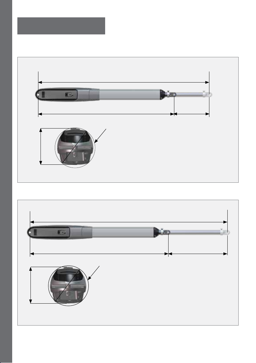
3.1. Physical Dimensions
970mm retracted
1370mm extended
95mm
Ø100mm
400mm
extended
piston stroke
500mm
extended
piston stroke
FIGURE 1. V 400 OVERALL DIMENSIONS
FIGURE 2. V 500 OVERALL DIMENSIONS
1570mm extended
95mm
1070mm retracted
Ø100mm
3. Specications
Questo manuale è adatto per i seguenti modelli
1
Indice
Altri manuali CENTURION SYSTEMS Apricancello


