8
Champion Pump Company, Inc • P.O. Box 528 • Ashland, OH 44805
Phone 419-281-4500 • toll free 800-659-4491 • fax 419-616-1100
With a ashlight, visually inspect the oil
in the motor housing (3) to make sure
it is clean and clear, light amber in color
and free from suspended particles. Milky
white oil indicates the presence of water.
Oil level should be just above the motor
when pump is in vertical position.
Seal Chamber - Drain oil from seal
chamber by placing pump on its side
with pipe plug (18) downward and
remove pipe plug (18). If the oil is found
to contain considerable water or other
contamination, the shaft seal (19) should
be inspected and replaced if required.
Oil Testing
• Drain oil into a clean, dry container by
placing pump on it’s side, remove cap
screws (6), lift conduit box assembly
(4) from motor housing (3). In sepatate
container drain seal chamber by
removing pipe plug (18).
• Check oil for contamination using an
oil tester with a range to 30 Kilovolts
breakdown.
• If oil is found to be clean and
uncontaminated (measuring above
15 KV. breakdown), rell the housing.
• If oil is found to be dirty or contaminated
(or measures below 15 KV. breakdown),
the pump must be carefully inspected
for leaks at the shaft seal, conduit box,
o-rings, pipe plug and pressure valve,
before relling with oil. To locate the
leak, perform a pressure test.
After leak is repaired, dispose of old oil
properly, and rell with new oil.
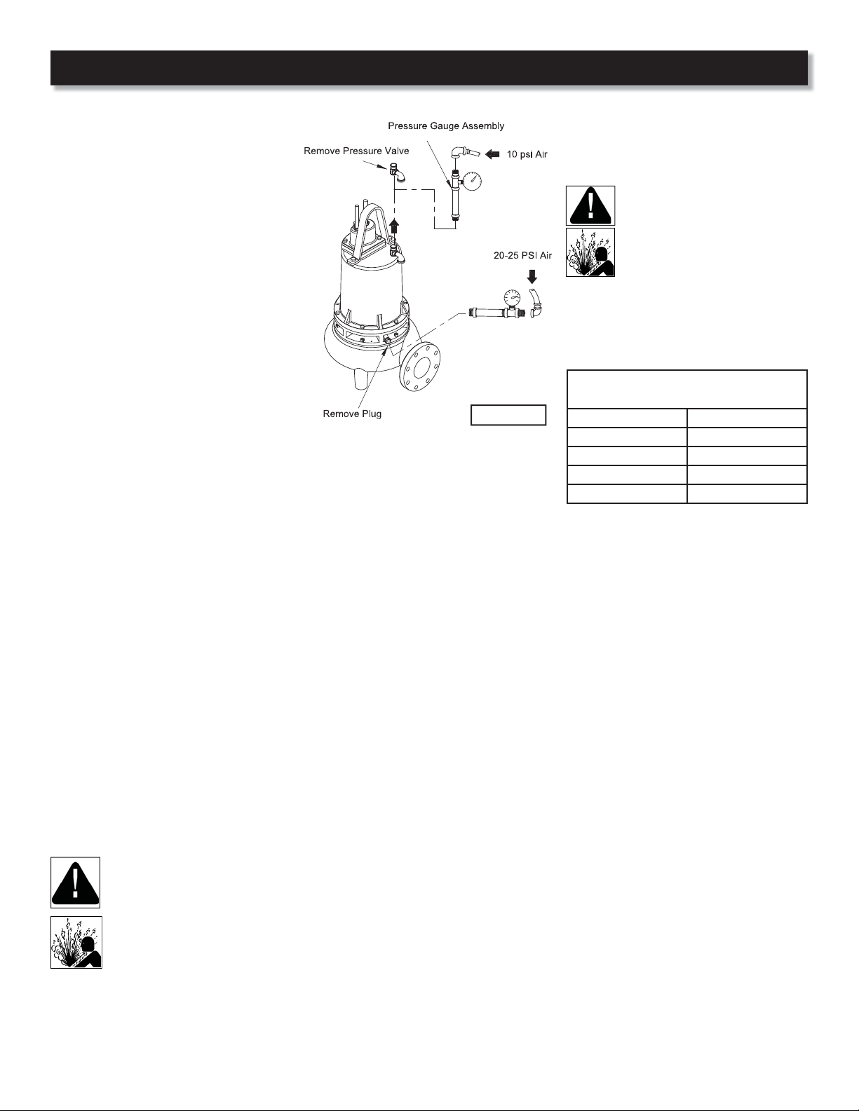
Pressure builds up extremely
fast, increase pressure by
“TAPPING” air nozzle. Too much
pressure will damage seal. DO
NOT exceed 10 P.S.I. in motor
housing and 20-25 P.S.I. in seal
chamber
Pressure Test
Motor Housing - Oil should be at normal
level. Remove pressure valve (10) from
motor housing (3). Apply pipe sealant
to pressure gauge assembly and tighten
into hole (See Figure 2). Pressurize motor
housing to 10 P.S.I. Use soap solution
around the sealed areas above the oil
level and inspect joints for“air bubbles”.
If, after ve minutes, the pressure is still
holding constant, and no“bubbles”/oil
seepage is observed, slowly bleed the
pressure and remove the gauge assembly.
Replace oil. Leek must be located and
repaired if pressure does not hold.
Seal Chamber - Check that seal chamber
is full of oil by removing pipe plug (18).
Apply pipe sealant to pressure gauge
assembly and tighten into hole in bearing
bracket (16). Pressurize seal chamber to
20-25 PSI and check for leaks.
Oil Replacement - Set unit upright and
rell with new cooling oil as per table.
Fill to just above motor as an air space
must remain in the top of the housing to
compensate for oil expansion. Reassemble
the o-ring (5) and conduit box (4) to motor
housing (3).
Apply thread locking compound to cap
screws (6) and place into holes and torque
to 15 ft/lbs.
DO NOT overll oil. Overlling
of housing with oil can create
excessive and dangerous hydraulic
pressure which can destroy the
pump and create a hazard.
Overlling oil voids warranty.
Oil Replacement: Seal Chamber - Rell
chamber completely full with new cooling
oil or reuse the uncontaminated oil.
Cooling Oil
Recommended Supplier/Grade
BP Enerpar SE100
Conoco Pale Parafn 22
Mobile D.T.E. Oil Light
Shell Canada Transformer-10
Texaco Diala-Oil-AX
Disassembly
Impeller & Volute - Disconnect power.
Remove hex nuts (24) and vertically lift
motor housing and seal plate assembly
from volute (31). Clean out volute (31)
if necessary. Inspect gasket (30) and
replace if cut or damaged. Clean and
examine impeller (27), for pitting or
wear and replace if required. To remove
impeller (27), remove cap screw (29) and
washer (28). With a wheel puller, pull
impeller straight o shaft and remove
square key (13).
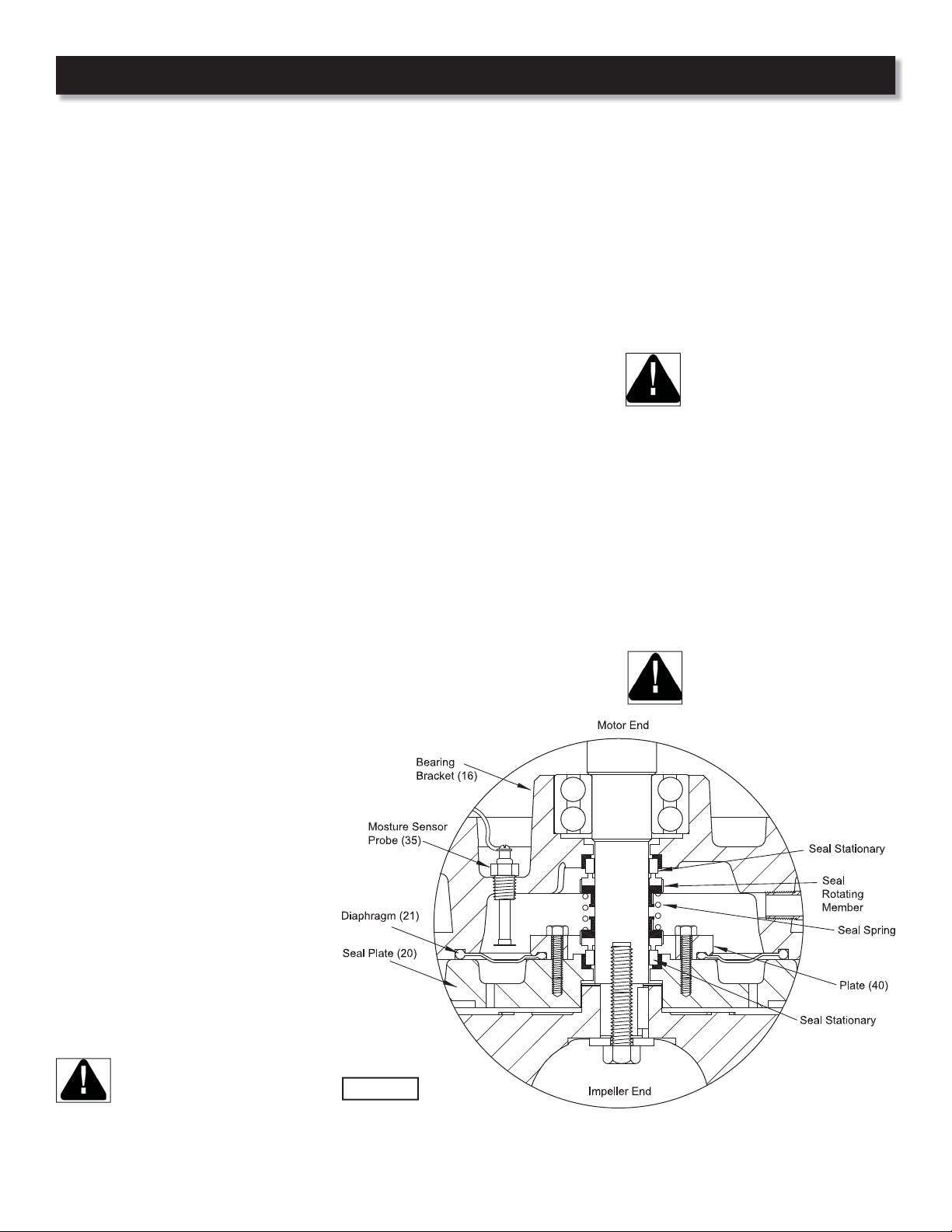
Moisture Probes - Drain oil from seal
chamber, if not already done. Remove
cap screws (9) and lifting handle (8). Set
unit upside down on blocks to avoid
damaging cables. Remove socket head
cap screws (22) and lift seal plate (20),
with seal’s (19) stationary, vertically from
bearing bracket (16), do not damage
seal. Check moisture sensor probes (35)
for damage, replace by removing screws
(38) and disconnecting wires (34). Then
remove probes (35) from bearing bracket
(16).
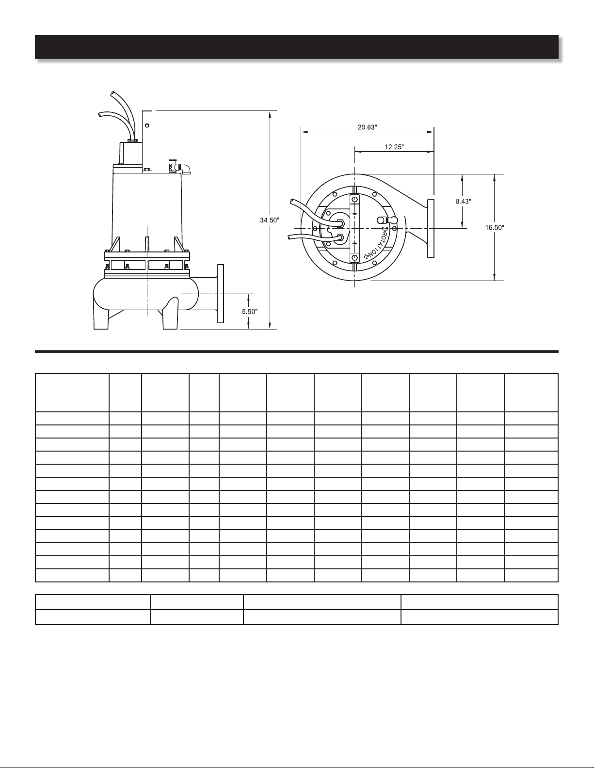
Figure 2
Service