
Chint Power CPS Series Manuale utente
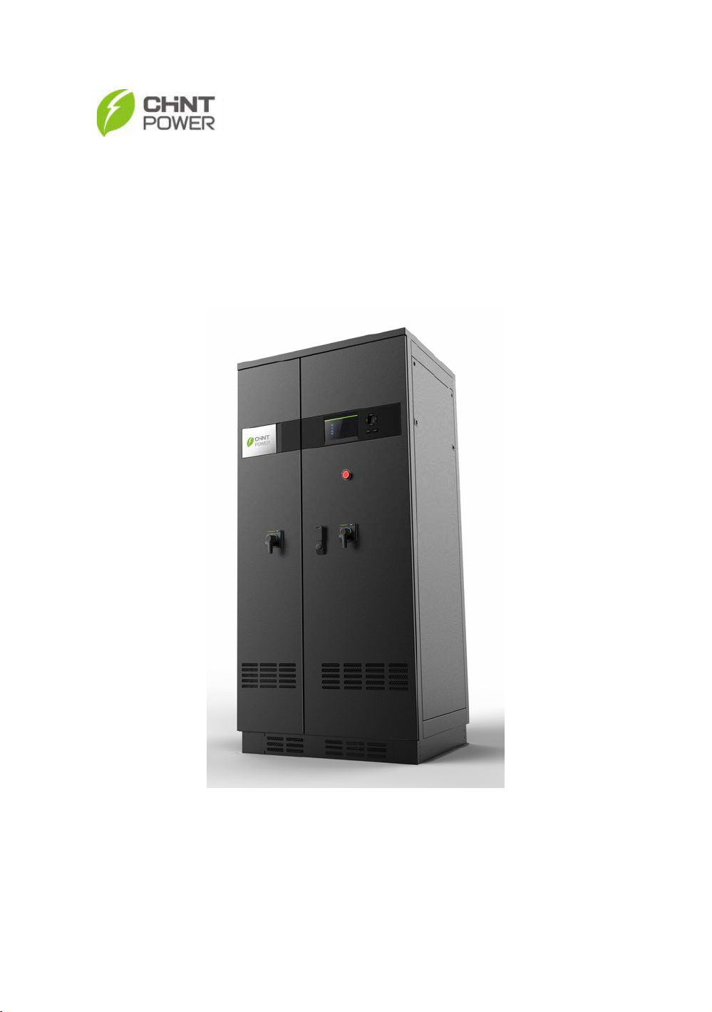
CPS Series Photovoltaic Grid Connection
Inverter CPS SC100KT
Installation and Operation Manual
Shanghai CHINT Power Systems Co., Ltd.

Table of Contents
Chapter 1 Safety Instructions............................................ 1
Chapter 2 Overview........................................................... 3
2.1 Photovoltaic system for grid connection .............. 3
2.2 Inverter circuit structure....................................... 4
2.3 Illustration for front and top views........................ 5
Chapter 3 Installation........................................................6
3.1 Basic requirements.............................................. 6
3.2 Mechanical installation ........................................ 6
3.3 Electrical installation ........................................... 9
3.3.1 DC connection.........................................10
3.3.2 AC connection .........................................12
3.3.3 Communication connection .....................13
Chapter 4 Operation ....................................................... 15
4.1 Start-up and shut-down ......................................15
4.1.1 Start-up....................................................15
4.1.2 Shutdown ................................................15
4.2 Operation mode..................................................16
4.3 Grid connection and power generation...............18
4.4 Fault shutdown ...................................................19

2
Chapter 5 Human Machine Interface ...............................28
5.1 Description of LCD display ..............................28
5.2 Operation State ..................................................29
5.3 Interface and menu functions .............................30
5.3.1 Interface types ........................................30
5.3.2 Main operation interface..........................32
5.3.3 Operation information..............................33
5.3.4 Present fault............................................34
5.3.5 History.....................................................34
5.3.6 System setup ..........................................36
5.3.7 System protection parameter setup ........37
Chapter 6 Technical Data ................................................40
Chapter 7 Quality Assurance ...........................................42
7.1 Warranty.............................................................42
7.2 Disclaimer ..........................................................42
7.3 Quality clause (Warranty clause)........................42
Chapter 1 Safety Instructions
1
Chapter 1 Safety Instructions
Please read this manual carefully before installation. CPS
reserves have the right not to guarantee the quality for
equipment damage if the user fails to install the equipment
as per the instructions in this manual.
Electric shock hazard:
Make sure that all DC and AC are isolated from the
equipment to prevent electric shock hazard during
equipment maintenance or installation. At the same time,
make sure that equipment is grounded properly.
Warning:
All operations and wiring should be performed by qualified
technical personnel.
When the connected solar cell panel is exposed to the
sunlight, it generates DC voltage and charges the DC bus
capacitors of the inverter. Electric charges are still stored in
the capacitors even the input of the photovoltaic inverter is
Chapter 1 Safety Instructions
2
switched off. Therefore, equipment shall not be serviced or
operated until 60 minutes after all inputs are switched off.
For grid connection only!
This inverter is specially designed for directly connecting AC
power to public power grid. Do not connect the AC output of
this equipment directly to private AC power equipment.
High temperature:
This product complies with the international safety standard,
but the inverter would generate heat during operation. So do
not touch the metal surfaces of the radiator and inverter
during the operation of the inverter.
Chapter2 Overview
3
Chapter 2 Overview
2.1 Photovoltaic system for grid connection
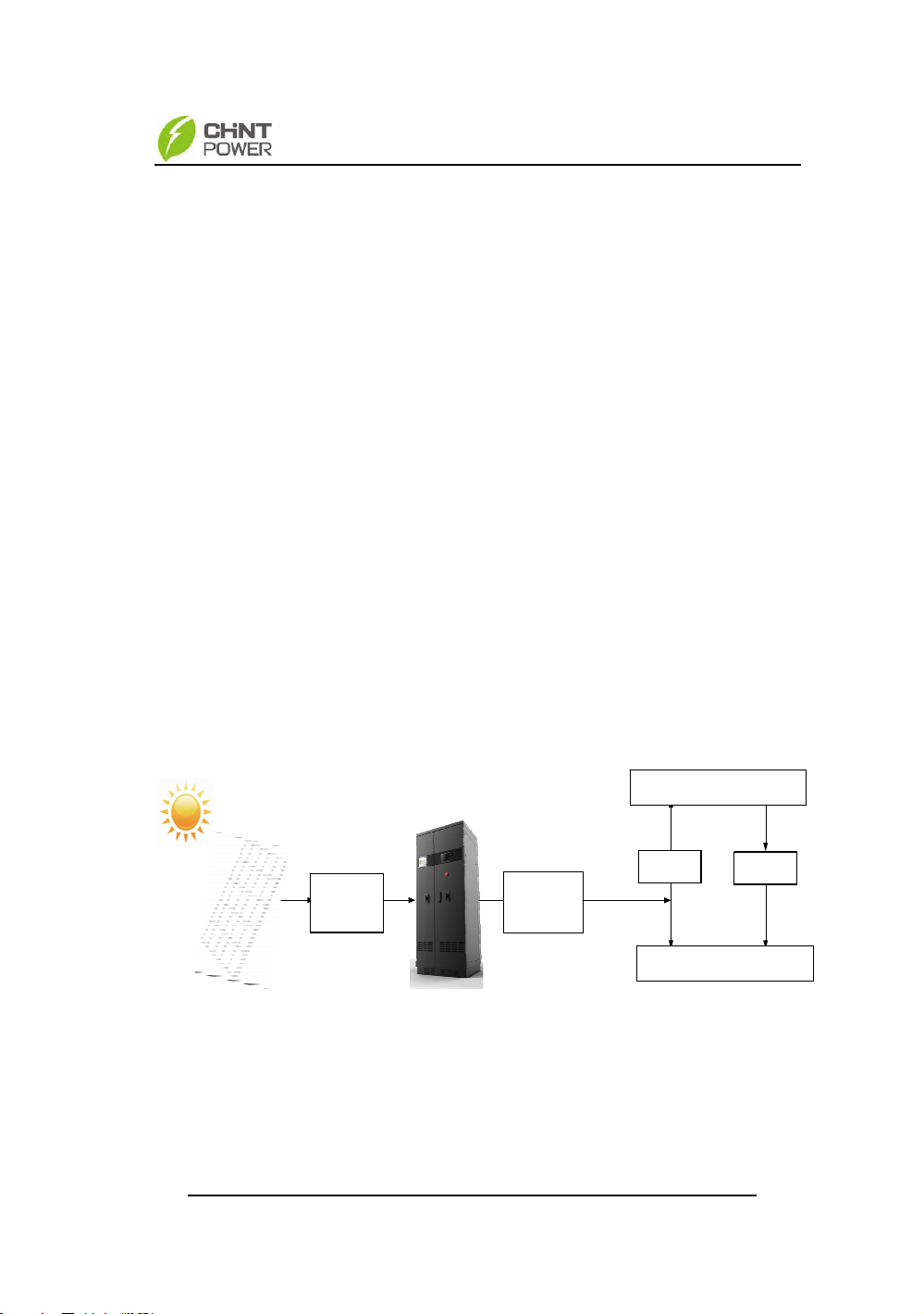
CPS SC100KT grid connection photovoltaic inverter
applies to all kinds of commercial roof grid connected system
or grid connected power station system. Normally, the
system consists of solar cell modules, DC power distribution
unit, grid connection inverter and AC power distribution unit
(Figure 2-1). Solar energy is converted to direct current
through solar cells. The direct current is then converted to
alternative current with the same frequency and phase as
the grid through grid connection inverter. All or part of the
alternative current is supplied to the local load. The
remaining or all electricity is fed to the grid.
Figure 2-1 Grid connection photovoltaic power generation system
DC power
distribution
unit
AC power
distribution
unit
Metering
out
Metering
in
AC load
AC grid
Chapter 2 Overview
4
2.2 Inverter circuit structure
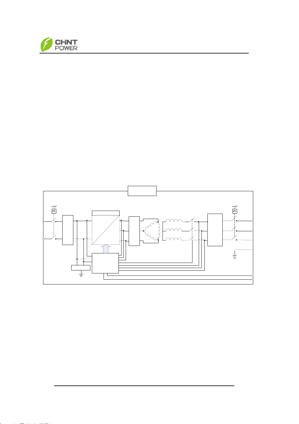
The basic schematic diagram of CPS SC100KT inverter
is shown in Figure 2-2. The output of solar cells first passes
through DC switch and DC EMI wave filter circuit. The
inverter then converts DC voltage to 3-phase AC voltage.
The output wave filter will remove high frequency component,
and is connected to LV grid through industrial frequency
transformer step-up and isolation, AC contactor, AC EMI
wave filter and circuit breaker.
Figure 2-2 Schematic diagram
DC EMI Filter
Surge Protector
Inverter
AC EMI Filter
Surge Protector
L1
L2
L3
PV+
PV-
=
3 ~
ISO Detection
Sine Wave Filter
Control
&
Monitor
G
CPS SC100T
Ipv
Upv+
Upv-
Ia
Ib
Ic
JCQ
Uab
Ubc
Uca
PWM
RS485+
RS485-
Chapter2 Overview
5
2.3 Illustration for front and top views
Figure 2-3 Appearance sketch
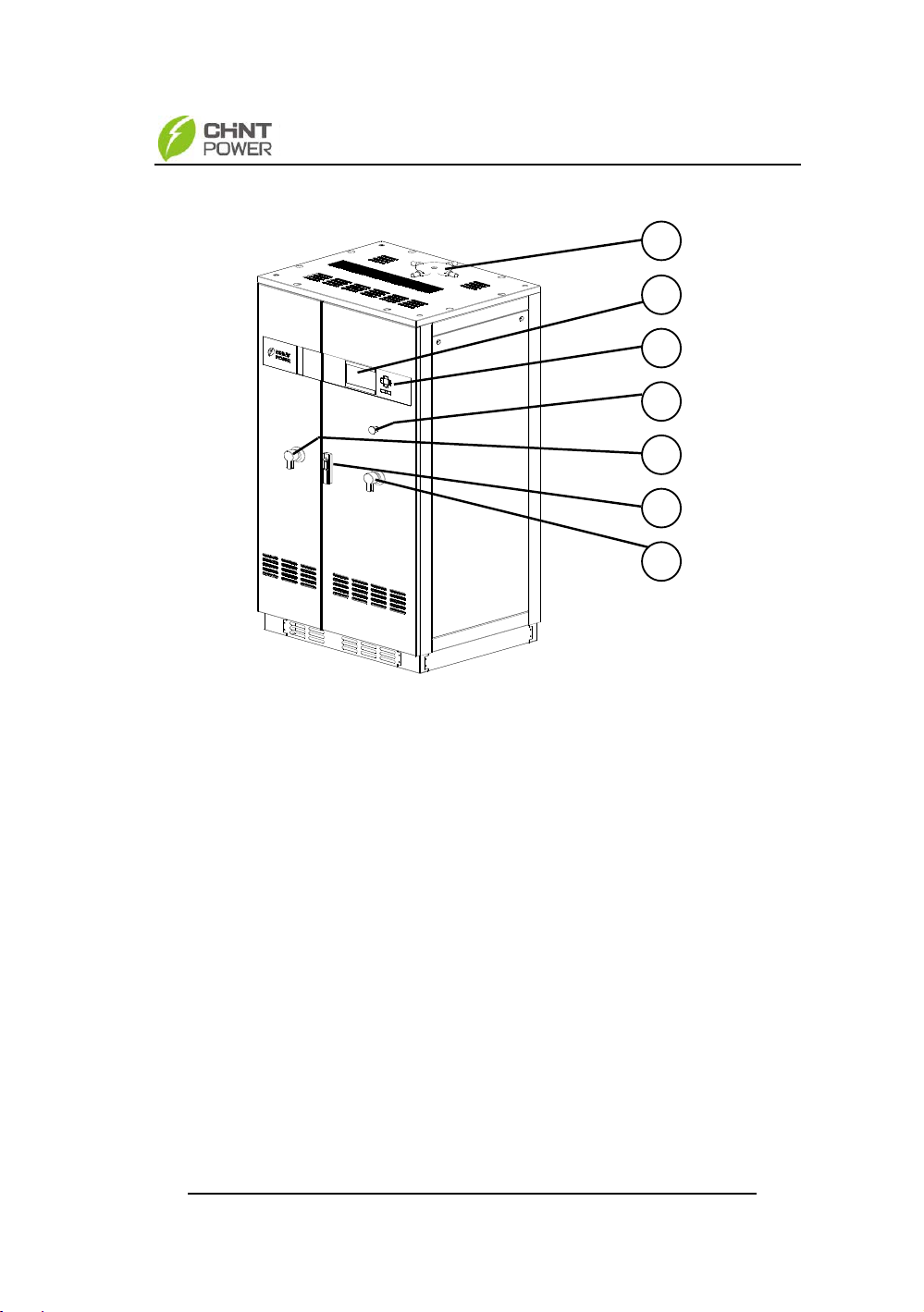
Description of main items (shown in Figure 2-3):
1、Mounting plate for lifting ring
2、Display panel (with LED indication and LCD Display)
3、Operation keys (Up, Down, Left, Right, ESC, ENT)
4、Emergency switch button
5、Switch on DC side
6、Lock
7、Switch on AC side
1
7
2
6
4
5
3

Chapter 3 Installation
6
Chapter 3 Installation
3.1 Basic requirements
The protection level of CPS SC100KT photovoltaic
inverter is IP20. Do not install it in a humid environment.
Check and make sure that the ambient temperature
of the installation location is -20 C ~+65C;
Make sure that the commercial power grid voltage is
320~460Vac, 50Hz;
Grid connection permit has been obtained from the
power authority;
Installation personnel must be qualified electricians
or have under gone professional trainings;
Sufficient convection space;
Away from flammable and explosive substances
3.2 Mechanical installation
(1) Dimensions
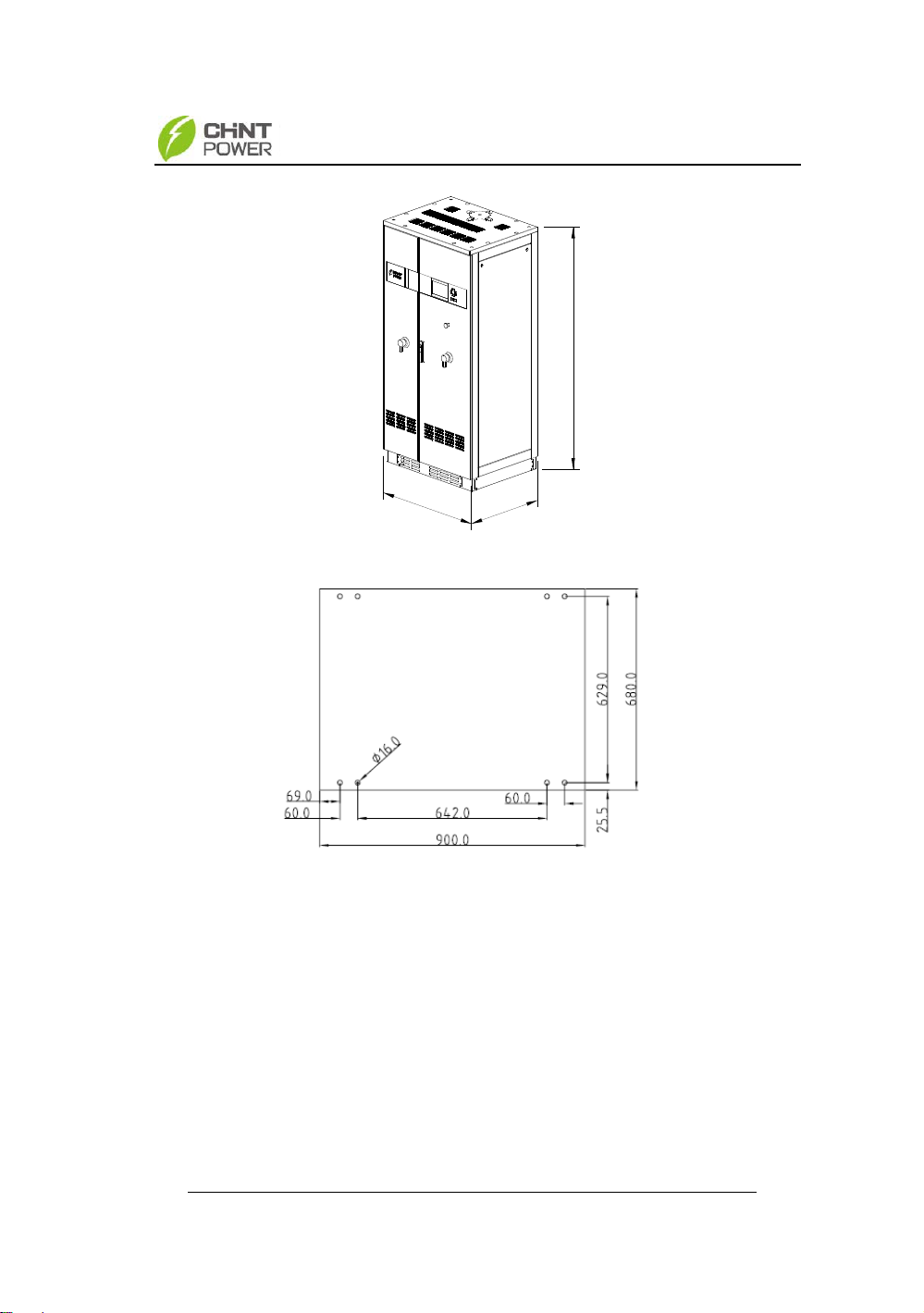
Dimensions of CPS SC100KT photovoltaic inverter are
shown in Figure 3-1.The dimensions of foundation
installation are shown in Figure 3-2.
Chapter 3 Installation
7
920
726
1900
Figure 3-1 Sketch of dimensions
Figure 3-2 Sketch of foundation installation dimensions
(2) Requirements on inverter installation:
Front door: A 560mm space should be reserved to
ensure that the front door can be opened and closed freely.
Back: A 600mm space should be reserved to allow for
maintenance.
Top: A 600mm space should be reserved for heat
dissipation.
Questo manuale è adatto per i seguenti modelli
1
Indice
Altri manuali Chint Power Invertitore

Chint Power
Chint Power CPS SCA50KTL-DO/US-480 Manuale utente

Chint Power
Chint Power CPS PSW1.5M-1500V Manuale utente

Chint Power
Chint Power CPS SCH Series Manuale utente

Chint Power
Chint Power CPS SCE4 Manuale utente

Chint Power
Chint Power CPS SCA25KTL-DO Manuale utente

Chint Power
Chint Power CPS SCE4KTL-O/US Manuale utente

Chint Power
Chint Power CPS SC2.8KTL Manuale utente


