
Clear Water Zodiac LM2 Series Manuale di programmazione

LM2/LM3 Series
Troubleshooting Manual

2
READ AND FOLLOW ALL INSTRUCTIONS.
This manual is for use by licensed electricians or trained pool professionals only. No other person is to install,
service or troubleshoot the LM Series Chlorinators.
ELECTRICAL HAZARD
• Toreduceriskofelectricalshock
- MakesureallpowertopoolequipmentareaisoffpriortoanyinstallationorremovalofClearwatercomponents.
- Replacedamagedpowerpackcordimmediately.
- Donotburycord.Locatecordtominimizeabusefromlawnmowers,hedgetrimmersandotherequipment.
• Severeshockorinjurywilllikelyoccurasaresultofadrillordrillcordcomingincontactwithwater.Neverallowelectricdrillorcordtocome
incontactwithwater.OnlyplugdrillintoaClassA(5MilliampereTrip)protectedGroundFaultCircuitInterrupter(GFCI)inaccordancewith
theNationalElectricalCodeSection680(USAonly).Pleaseseeyourdrillowner’smanualforfurthersafetyprecautions.
• Installthepowerpackatleast10feetfromtheinsidewallsofapooltopreventanypossibilityoftheunitcomingincontactwithwater.
• YourClearwaterChlorinatorhasbeendesignedwithanelectronicflowswitch.Thisdeviceautomaticallyswitchesthechlorinator‘OFF’
whenthewaterthroughthecellstops.Topreventcelldamageandpersonalinjury,donotinanywayinterferewiththissystemwhichhas
beendesignedforyourprotection.
CHEMICAL USE HAZARD
• Toavoidpersonalinjurywhenworkingwithpoolchemicals,alwayswearrubberglovesandeyeprotectionandworkinawell-ventilatedarea.
Usecautionwhenchoosingalocationtoopenandusechemicalsastheymaydamageanysurfaceinwhichtheycomeincontact.
• Theadditionofcertainchemicalscanreducetheeffectivenessofchlorine.Alwaysmakesurethatproperresidualchlorinelevelsare
maintainedtoavoidpersonalinjury.
• Thisproductmanufactureschlorine.Individualswithanytypeofchlorinesensitivityshouldtaketheappropriateprecautionstoavoidinjuryor
illness.
EQUIPMENT WATER PRESSURE HAZARD
• AlwaysturnpumpoffpriortoinstallingorremovinganyClearwatercell.Yourpump/filtersystemisoperatedunderpressureandthe
pressuremustbereleasedbeforeyoubeginwork.Pleaseseeyourpump/filterowner’smanualforfurtherinstructions.
• Toavoidcelldamage,waterpressureinthecellmustnotexceed29psi(200kPa)
PREVENT CHILD INJURY AND DROWNING
• Toreducetheriskofinjury,donotpermitchildrentooperatethisproduct.
• Donotletanyone,especiallysmallchildren,sit,step,lean,orclimbonanyequipmentinstalledaspartofyourpool’soperationalsystem.
Unlessotherwisestated,ALLcomponentsofyourpool’soperationalsystemshouldbelocatedatleast3feetfromthepoolsochildren
cannotusetheequipmenttogainaccessandbeinjuredordrown.
IMPORTANT SAFETY INFORMATION
• Chlorinatormustbeinstalledandoperatedasspecified.
• Scratchingorbendingplatesincellhousingcanreducecelllife.
• PowertotheLM2orLM3shouldbeturnedoffbeforeunpluggingthecellconnectorstopreventcelldamageandlowvoltagesparks.
• Keepthecellterminalsprotectedwithalightcoatingofsiliconegreasetoallowforapositiveelectricconnection.Useofanyothertypeof
greasemaydamagetheterminalsealsand‘o’rings.Donotimmersetheseterminalsinacidwashsolution,andavoidaccidentalcontact
withsaltwater.
• Waterabovethetemperatureof104degreesF(40degreesC)flowingthroughthecellcancauseplasticcelltodiscolor.
• Powerpackmustnotbeinstalleddirectlyaboveanyotherheatsourcesuchasfilter,pumporheater.Itmustbeatleast1Ft.(300mm)
fromthegroundtoallowfreecirculationofairaroundit.Itmustnotbeinstalledinaclosedbox.Ifthepowerpackistobeinstalledon
apost,thenitmustbecentrallypositionedonaflatpanelofsuitablewaterproofmaterialatleast10inches(240mm)wideand18inches
(440mm)high.
• Checkthecellfrequentlytopreventtheaccumulationofpooldebristhatforanyreasonmayhaveby-passedthepoolfilter.
CAUTION Failure to heed the following warnings could cause damage to pool equipment
or personal injury.
!
WARNING Failure to heed the following warnings can result in permanent injury,
electrocution or drowning.
!

3
Table of Contents
Safety Instructions .............................2
Look /Feel....................................3
Circuit Breaker ................................4
Power Cord...................................4
Testing Power Path ............................5
Chlorinator Not Operating........................6
No chlorine reading ............................7
Output Lights will Not go to 100% .................8
Output Lights will Not go Down ...................9
Amber Output Light Blinking......................9
Transformer ..................................9
No Flow Light Is On ...........................10
Add/Check Salt Light Is On .....................11
Add Salt Light and Green Lights Are On ...........11
Chlorine reading too high .......................12
Calcium Build-up On Cell .......................12
Reversing Polarity ............................13
Cleaning/Replacing Cell ........................13
LM3 Interface Instructions ......................14
Touch Pad PCB ..............................15
PC Board Replacement for the LM2-15/LM3-15 .....16
PCB Replacement for LM2-24/3-24 or 2-40/3-40.....17
Triac Screws.................................18
LM2 Exploded Diagram & Parts List...............19
LM3 Exploded Diagram & Parts List...............20
Look/Feel
Before removing chlorinator cover, check the following:
1. Is the pool pump on?
2. Is the chlorinator turned on?
3. Do the indicator lights function? (If NO, see Output Lights pg. 8-9)
If all of the above answers are “YES”, there is no problem with the chlorinator. Have the consumer bring a water
sample to their dealer for analysis.
4. Is the circuit breaker tripped? (see Circuit Breaker pg. 4)
5. LM2 - Is the output cord attached to the cell & the blue sensor wire attached to the sensor post on the cell?
(see No Flow Light Is On. pg. 10)
LM3 - Is the plug cap attached to the cell?
6. Can you see the cell producing? (it looks like effervescence)
7. Is there calcium built-up on the cell? (see Calcium Build-up on Cell pg. 12)
After checking the above items:
1. Turn off power supply.
2. Remove chlorinator from wall if needed.
3. Remove screws (4) to remove cover and check the following:
• Arethereanyvisibleburnmarks?
• Isthereanyvisiblewaterdamage?
• Arethereanyloosewiresorscrews?

4
Circuit Breaker
Reset Circuit Breaker
1. Turn off power supply.
2. Remove chlorinator from wall.
3. Find circuit breaker on bottom near power cord.
4. Push button in.
5. Replace chlorinator on wall.
6. Turn on power supply.
Replace Circuit Breaker
1. Disconnect power supply.
2. Remove chlorinator from wall.
3. Remove 4 screws to remove cover.
4. Disconnect ribbon wire connector from power PCB and set cover aside.
5. Remove 2 push-on wire connectors from back of circuit breaker.
6. Use pliers to squeeze base of circuit breaker and push through hole from the inside.
7. Push new circuit breaker through hole from the outside till it snaps in place.
8. Reconnect 2 push-on wires to back of circuit breaker.
9. Reconnect ribbon wire connector to power PCB.
10. Replace cover with 4 screws.
11. Replace chlorinator on wall.
12. Connect power supply.
Power Cord
Power Cord Replacement
1. Disconnect power cord from power source.
2. Remove chlorinator from wall.
3. Remove 4 screws to remove cover.
4. Disconnect ribbon wire connector from power PCB and set cover aside.
5. Remove 3 Push-on wire connectors and unscrew ground wire from back.
6. Use pliers to squeeze base of power cord holder and push through hole from the inside.
7. Unclip power cord holder and transfer to new power cord.
8. Push power cord holder with new power cord through hole from the outside till it snaps in place.
9. Reconnect 3 push-on wire connectors and screw ground wire to back.
10. Reconnect ribbon wire connector to power PCB.
11. Replace cover with 4 screws.
12. Replace chlorinator on wall.
13. Connect power cord to power source.

5
Testing Power Path
1. Turn off power supply.
2. Remove chlorinator from wall.
3. Remove 4 screws to remove cover (support cover and leave ribbon wire connected to power PCB).
4. Turn on power supply.
5. Use multimeter set on AC volts to test between A & B.
Results=220V?
YES NO
Unitreceivingpower–continuetesting. Havequalifiedelectricianrewire
chlorinatorto220Vordetermine
whynovoltage.
Replacecircuitbreaker.
(see Circuit Breaker pg. 4)
Transformerreceivingpower
circuitbreakerOK(continuetesting).
6.TestbetweenA&C=220V?
YES NO
7.TestbetweenD&EandE&F
Resultsshouldbeasprintedontransformer(this
varies for different models).
(Depending upon the type of transformer, this
test may be done at the PC board.)
Both tests read OK?
YES NO
Transformerisgood.
Replacetransformer.
(see Transformer pg. 9)
D E F
A
B
C
D F E

6
Chlorinator Not Operating
Arethereanylightsvisible?
YES NO
Seepg.8. PushOn / Off Button
orturnonLM3viacontroller
Istheresettablecircuitbreakertripped?
YES NO
Resetcircuitbreaker.
(see circuit breaker pg. 4)
*Ifbreakercontinuestotrip
replacePCboard(see pg. 17)
andcircuitbreaker(see pg. 4).
Refercustomertoaqualified
electriciantotroubleshoot
powersource.
Istherepowerattimerorswitch?
YES NO
Tracepowerthroughtransformer.
(see Transformer pg. 9)
ChecktouchpadPCB.
(see Touch Pad PCB pg. 15)
ReplacepowerPCB.
(see Power PCB pg. 17)
Checkforloosewires.

7
No Chlorine Reading
Arethereanylightsvisible?
YES NO
Seepg.6.
Willtheoutputlightsgoallthewayup?
YES NO
Chlorinatorisworkingproperly.Recommend
tocustomertohavewatersample
checkedbydealer.
Addsaltaccordingtochartin
Owner’sManual.
1.Issaltlevel4000ppm?
YES NO
Havequalifiedelectrician
wireto220V.
2.Isunitwired220V?
YES NO
3.Doescellmodel/size
matchpowerpack?
YES NO
Replacewithcorrectcell.
4.Thecellisnearingtheendofitslife.
Replacecell.

8
Output Lights Will Not Go to 100%
Issaltlevel4000ppmorhigher?
YES NO
Addsaltaccordingtochart
inOwner’sManual.
Checkthereis220Vincomingpower.
YES NO
Iswatertemperaturebelow65°F?
YES NO
Addsalttocompensate.
Cellmaybenearingtheendofitslife.Check
cellage,runtime&outputsetting.
Replacecell.(see Cell pg. 13)
For LM3 Models
InsureLM3isproperlyinterfaced.(seepg.
14)Checkoutputsetting&runtimeofLM3at
controllerremotepad.Increaseasneeded.If
outputandruntimewereadequate,disconnect
communicationwireatLM3touchpad.LM3
nowoperatesasastandaloneunitwith
theoutputbuttonsontheLM3powerpack
controllingtheoperation.
Ifunitislessthan1yearoldcheck
thefollowing:
ChecktouchpadPCB.
(see Touch Pad PCB pg. 15)
ReplacepowerPCB.
(see Power PCB pg. 17)
Havequalifiedelectrician
rewirechlorinatorto220V.
Reconnectcommunicationwire.
InterfaceLM3withcontroller.
Adjustoutputandruntime.

9
Output Lights Will Not Go Down
IsChlorinatorinsuper-chlorinatemode?
YES NO
Presssuper-chlorinatebuttononcetotake
chlorinatoroutofsuper-chlorinatemodeor
adjustatcontrollerremote.
ChecktouchpadPCB.
(see touch pad PCB pg. 15)
Amber Output Light Blinking
Chlorinatorisinarestmodebeforeit
reversespolarity.Wait5-10minutes
andcheckagain.
OR
Pressandholdservicebutton
(locatedunderthe“C”inCLEARWATER)
tospeedupthereversingprocess.
(see Reversing Polarity pg. 13)
Transformer
Testing
(see Testing Power Path pg. 5)
Replacement
1. Disconnect power supply.
2. Remove chlorinator from wall.
3. Remove 4 screws to remove cover.
4. Remove ribbon wire connector from power PCB and set cover aside.
5. Disconnect from the three white plastic terminals all wires that lead to the transformer (keep track of each wire
location for reassembly).
6. Remove screw from the center of each 4-way terminal and pull the PCB to the side.
7. Remove the rivets holding the transformer in place.
8. Mount new transformer using new rivets.
9. Relocate PCB and both 4-way terminals to top of transformer and mount with screws.
10. Attach wires from new transformer to correct plastic terminals.
11. Attach ribbon wire connector.
12. Attach cover with 4 screws.
13. Replace chlorinator on wall.
14. Reconnect power supply.
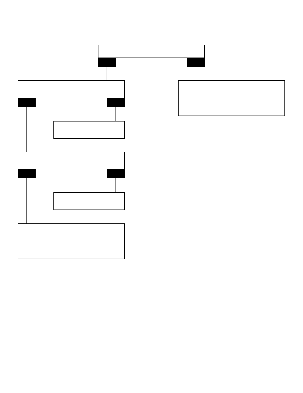
10
No Flow Light Is On
Isthepumpmovingwater?
YES NO
Thereisaflowrelatedproblem
withpoolequipment.
Disconnectsensorclipuntilpool
equipmentisrepaired.
Isthebluesensorwireattached
andingoodcondition?
YES NO
Repair/attachbluesensor
wireendtosensoroncell.
Isthereabubbleexposingthe
sensorinsidethecell?
YES NO
ReplacePowerPCB.
(See pg. 17)
Thereisaflowrelatedproblem
withtheequipment.
Disconnectthesensorwireuntilpool
equipmentisrepaired.
Questo manuale è adatto per i seguenti modelli
1
Indice
Altri manuali Clear Water Filtro per piscina


Manuali Filtro per piscina popolari di altre marche


Davey
Davey EcoPure DEP2140 Manuale utente

JUWEL Aquarium
JUWEL Aquarium EccoSkim Manuale utente

POLYGROUP LIMITED
POLYGROUP LIMITED SFS600 Filter System with F600C Pump Manuale utente

Pentair Pool Products
Pentair Pool Products Filter CFW Series Manuale utente

Oase
Oase Skimmer 250 Manuale utente

Oase
Oase CrystalSkim 350 Manuale utente