4
CLIMATEMASTER WATER-SOURCE HEAT PUMPS
DOAS CM3500 Controller
Rev.:31 July, 2013
ClimateMaster Water-Source Heat Pumps
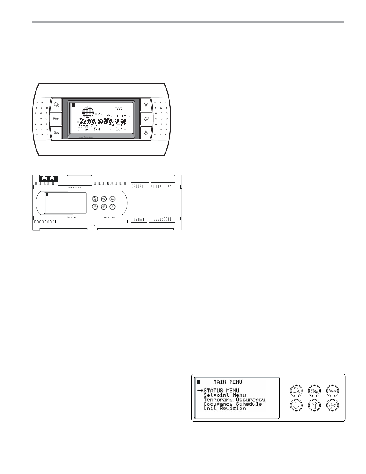
Your ClimateMaster controller is designed for precise
monitoring and control of air temperature and relative
humidity (RH) within a conditioned environment. This
CM3500 control system is easy to install and operate. It
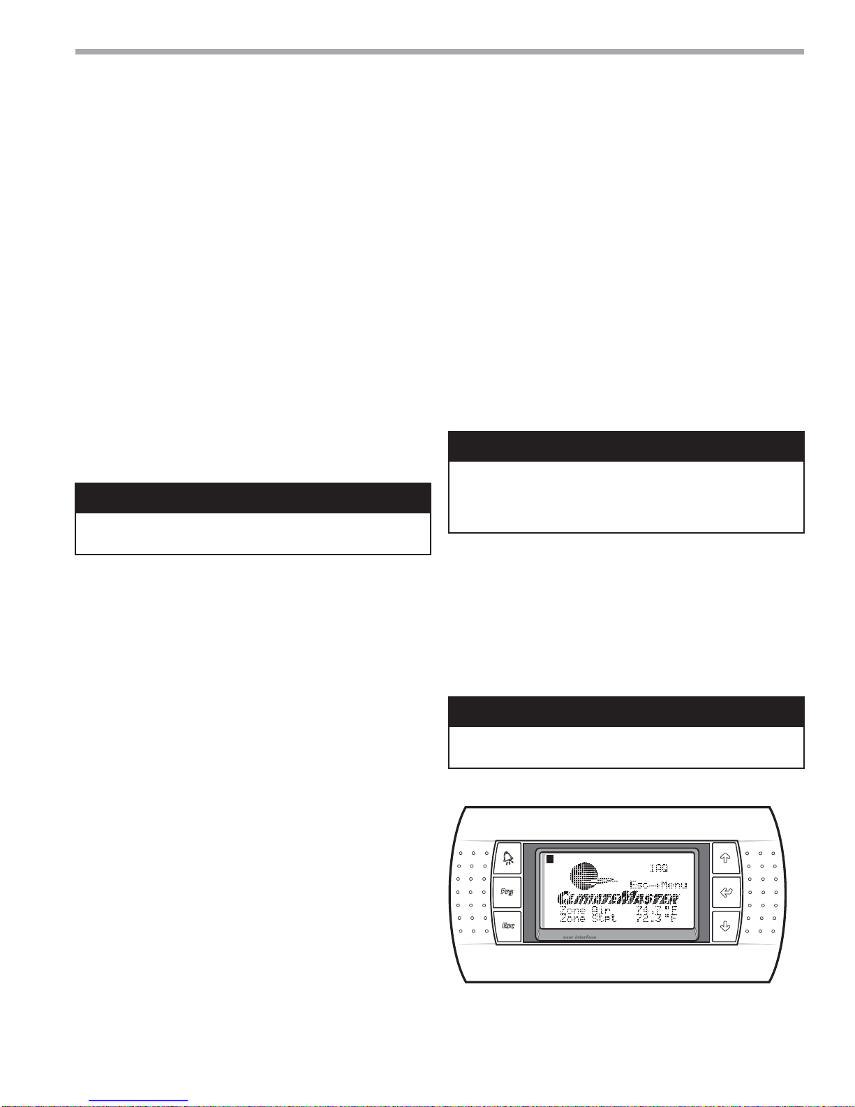
features either an internal display terminal (IDT), as part of
the controller, or a wall-mountable remote display terminal
(RDT), in cases where the controller mounted display or IDT
would prove hard to view or use. Both allow you to view and
adjust setpoints and modes of operation. They also indicate
the operating status of major components inside of the
dehumidifier. Most sensors and inputs have been factory-
installed and wired inside of the dehumidifier. In most cases,
you need only mount and wire the supply air temperature
sensor and, if provided, the RDT. The RDT, which is simply
an interface tool, contains no sensors. You do not need to
install it in the room you wish to dehumidify. If purchased
with your system, CO2 and remote room sensors may
require mounting as well.
Your controller is provided with a duct-mountable
temperature sensor for the supply air. If the unit was
purchased with the zone reset option, it also has one or
multiple remote room sensors. Additionally, if the unit
was purchased with the CO2 option, it has an indoor and
outdoor CO2 sensor.
• A duct-mount sensor is normally used in applications
where continuous blower operation is desired. A
duct-mount sensor helps ensure consistent conditions
throughout the space. Install the duct-mount sensor in
the supply air duct.
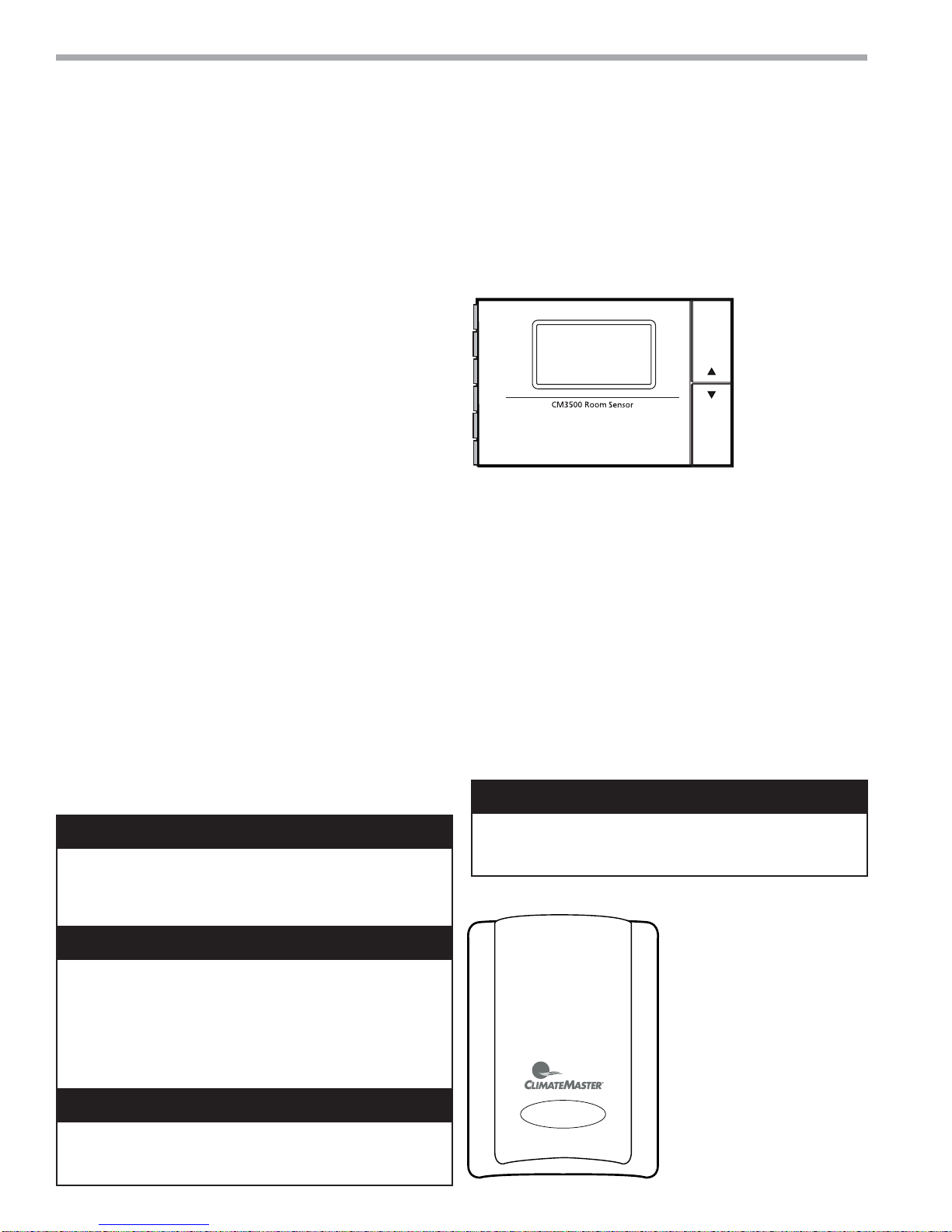
• ClimateMaster DOAS ordered with the zone reset
option are supplied with a remote room sensor. Up to
Installation
CAUTION! A potential drawback of this sensor is that it
relies on a continuous stream of air moving past it. Using a
duct-mount sensor with a non-continuous blower may lead to
short-cycling of the refrigeration compressor..
CAUTION! Undersized wiring will cause inaccurate sensor
readings. Do not run sensor wiring adjacent to, OR in the
same conduit as, wires carrying more than 24 VAC.
CAUTION! Do not mount the sensor in a section of duct where
false readings may occur due to dead air regions, solar heat
gain or thermal losses in winter. Do not mount the sensor where
water is likely to drip on it. Install two (2), 18 gauge (0-500 feet)
OR two (2), 24 gauge (0-100 feet) wires from the sensor to the
labeled terminal strip in the control panel of the dehumidifier.
(See your wiring schematic for connection details.)
CAUTION!
CAUTION!
CAUTION!
CAUTION! Undersized wiring will cause inaccurate sensor
readings. Do not run sensor wiring adjacent to, OR in the
same conduit as, wires carrying more than 24 VAC.
CAUTION!
Figure 1: CM3500 Room Sensor
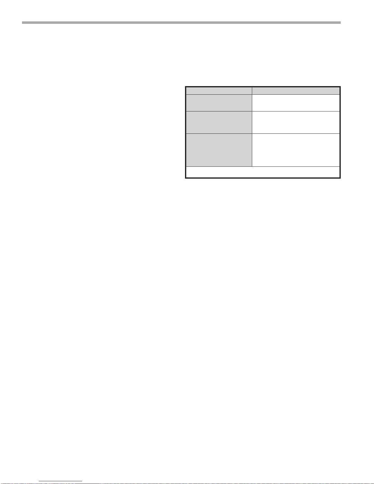
Figure 2: CO2 Sensors
four of these sensors may be wired to the system.
This wall-mountable display is an IP30 rated device
Operating conditions must be between 32.0°F and
120.0°F and less than 85% RH. The controller’s RS485
serial interface communicates via three-way plug-in
terminals. Install a twisted pair plus shielded cable,
20-22 AWG. Total length of the network must not
exceed 1,500 feet. The capacitance between the wires
must not exceed 90 pF/M. (See your wiring schematic
for connection details.) These remote devices require
a separate 24Vac 50/60HZ 1.5VA power connection.
Provide a dedicated 250 mAT fuse for each sensor.
Use a class 2 safety transformer with a minimum
rating of 4VA. If the sensor is wired to F1 and F2 of
the dehumidifier control panel terminal, G0 must be
connected to F2.
• ClimateMaster DOAS ordered with the CO2
control package require sensors for the indoor