Climax Technology vesta series Manuale utente

May-09-2017

TableofContents
1. INTRODUCTION __________________________________________________________________ 1
1.1. SYSTEM SPECIFICATION _____________________________________________________________ 2
2. PANEL INFORMATION _____________________________________________________________ 4
2.1. IDENTIFYING THE PARTS: _____________________________________________________________ 4
2.2. THE POWER SUPPLY: _______________________________________________________________ 5
2.3. SYSTEM REQUIREMENTS: ____________________________________________________________ 5
3. GETTING STARTED _______________________________________________________________ 6
3.1. SYSTEM DEPLOYMENT ______________________________________________________________ 6
3.2. INSTALLATION _____________________________________________________________________ 6
3.3. SOFTWARE INSTALLATION ____________________________________________________________ 8
4. CONNECTION TO PANEL WEBPAGE _______________________________________________ 11
5. DEVICE MANAGEMENT __________________________________________________________ 13
5.1. LEARNING ______________________________________________________________________ 13
5.2. ADD RF DEVICE __________________________________________________________________ 20
5.3. LEARN RULE ____________________________________________________________________ 21
5.4. WALK TEST _____________________________________________________________________ 23
5.5. EXCLUSION _____________________________________________________________________ 24
5.6. Z-WAVE TOOL ___________________________________________________________________ 25
5.7. PSS CONTROL ___________________________________________________________________ 26
5.8. UPIC CONTROL __________________________________________________________________ 27
5.9. SURVEILLANCE ___________________________________________________________________ 28
5.10. GROUP CONTROL ________________________________________________________________ 29
5.11. SOUND/SIREN SETTING ____________________________________________________________ 30
6. PROGRAM THE SYSTEM _________________________________________________________ 34
6.1. PANEL CONDITION ________________________________________________________________ 34
6.2. PANEL SETTINGS _________________________________________________________________ 37
6.3. PIN CODE ______________________________________________________________________ 41
7. NETWORK SETTINGS ____________________________________________________________ 42
7.1. GSM (HSGW-G8 SERIES ONLY)______________________________________________________ 42
7.2. NETWORK ______________________________________________________________________ 45
7.3. WIRELESS ______________________________________________________________________ 46
7.4. UPNP _________________________________________________________________________ 47
8. SYSTEM SETTINGS ______________________________________________________________ 48

8.1. ADMINISTRATOR SETTING ___________________________________________________________ 48
8.2. HOME AUTOMATION _______________________________________________________________ 49
8.3. SCENE _________________________________________________________________________ 54
8.4. REPORTING _____________________________________________________________________ 56
8.5. CODE SETTINGS __________________________________________________________________ 59
8.6. SMTP SETTING __________________________________________________________________ 61
8.7. MEDIA UPLOAD __________________________________________________________________ 62
8.8. POLLING _______________________________________________________________________ 63
8.9. XMPP _________________________________________________________________________ 64
8.10. DATE & TIME ___________________________________________________________________ 65
8.11. DYNAMIC DNS __________________________________________________________________ 66
8.12. TEST IP _______________________________________________________________________ 67
8.13. FIRMWARE UPGRADE _____________________________________________________________ 68
8.14. RF FIRMWARE UPGRADE __________________________________________________________ 69
8.15. FACTORY RESET ________________________________________________________________ 70
8.16. BACKUP & RESTORE ______________________________________________________________ 72
8.17. SYSTEM LOG ___________________________________________________________________ 73
9. EVENT & HISTORY ______________________________________________________________ 74
9.1. CAPTURED EVENTS _______________________________________________________________ 74
9.2. REPORTED EVENTS _______________________________________________________________ 75
9.3. EVENT LOG _____________________________________________________________________ 76
9.4. DEVICE HISTORY _________________________________________________________________ 77
10. APPENDIX _____________________________________________________________________ 78
10.1. FAULT EVENT DESCRIPTION ________________________________________________________ 78
10.2. CONTROL PANEL MODE AND RESPONSE TABLE __________________________________________ 79
10.3. CROSS ZONE VERIFICATION ________________________________________________________ 81
10.4. FIRE VERIFICATION _______________________________________________________________ 81
10.5. CONTACT-ID PROTOCOL & FORMAT ___________________________________________________ 82
10.6. EVENT CODE ___________________________________________________________________ 83
1
1. Introduction
This section covers unpacking your IP Security System with HSGW Series IP Panel and
Security Sensors. Refer to later chapters for information on setting up and configuring the
system over the Web Page in more detail.
The advanced IP Security System with fully integrated TCP/IP technology and Ethernet
connectivity is able to take full advantage of new advances in IP Home Security and Home
Automation and multi-path signalling.
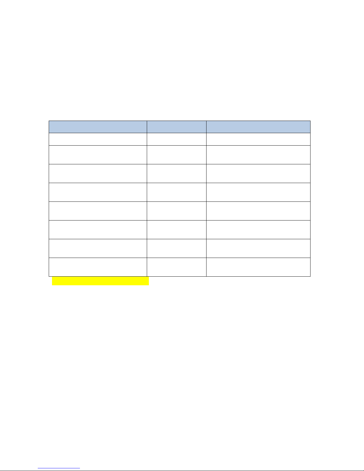
The HSGW Series include the following models:
Name Reporting Path Modules
HSGW-G1-4B/6B- S IP Reporting IP Gateway with built-in module
HSGW-G1-4B/6B-ZW IP Reporting IP Gateway with built-in Z-Wave
module
HSGW-G3-4B/6B- S-F1 433/ IP Reporting IP Gateway with built-in RF and
module
HSGW-G3-4B/6B-ZW-F1 433/ IP Reporting IP Gateway with built-in RF and
Z-Wave module
HSGW-G5-4B/6B- S-ZW IP Reporting IP Gateway with built-in and Z-Wave
module
HSGW-G8-6B- S-F1 433/ IP/GPRS Reporting IP Gateway with built-in RF, 3G, and
module
HSGW-G8-6B-ZW-F1 433/ IP/GPRS Reporting IP Gateway with built-in RF, 3G, and
Z-Wave module
HSGW-G15-4B/6B- S-ZW-F1 433/ IP Reporting IP Gateway with built-in , Z-Wave,
and RF modules
*4B = 4 batteries, 6B = 6 batteries

2
1.1. System Specification
Function
Zone Number 80 Wireless Zones (Includes up to 6 Remote Keypads and 20 Remote
Controllers)
Z-Wave devices
Devices
Zone Types Start Entry Delay, Burglar Follow, Burglar Instant, Burglar Outdoor, 24
Hours, Fire, Medical, Emergency, Emergency (Quiet), Water, Set/Unset,
Silent Panic, CO, Gas, Heat
For information on configuring Zone Groups, please see Appendix A
User PIN Codes 6 Users, 1 PIN Code each user (4-digits, number 0~9 ), available
combination from 0000~9999 (10000 different combinations, no
disallowed PIN Code )
Note: Input of 5 invalid User PIN codes at the remote keypad will lock
the remote keypad for 15 minutes.
Control Facilities Remote Keypad & Remote Controller
Home Portal Server
Report Destinations 20 Monitoring Stations or mobile number
Reporting Format Contact ID, SIA, SMS Text,
Arming Modes Away, Home 1, Home 2, Home 3
Alarm Type Burglar, Panic, Fire, Medical, Emergency, Water, Silent
Siren Timeout Programmable (3 min. by default), For Remote Keypad use only
Supervision Programmable time frame for inactivity alert
Special Function Tamper Protection
Real Time Clock (RTC) The Control Panel keeps and display time and date. This feature is also
used for the log file by providing the date and time of each event.
GSM Standards Compiles with CE & FCC standards.
Electrical
External AC adaptor 100-240V, 50/60Hz input, 9V 1A output (HSGW-X-4B series)
100-240V, 50/60Hz input, 12V 1A output (HSGW-X-6B series)
Power Supply Type PS Type A, not suitable for use external to supervised premises.
Backup Battery Ni-Mh 4.8V 1100mAH rechargeable battery pack (HSGW-X-4B series)

3
Ni-Mh 7.2V, 1600mAH rechargeable battery pack (HSGW-X-6B series)
APS fault Low Voltage SD
signal threshold
4.85 V ± 3% (HSGW-X-4B series)
7.5 V ± 3% (HSGW-X-6B series)
Battery Duration 6.5 hours for (HSGW-X-4B series)
13 hours or more for (HSGW-X-6B series)
Battery Recharge Time to
80% of 1100mAH/1600mAH 72 hours
Current Drain
AC Powered
Min: 94mA, Max: 103mA. (HSGW-X-4B series)
230mA standby, 639mA at full load. (HSGW-X-6B
series)
Battery Powered
Min: 167mA, Max: 183mA (HSGW-X-4B series)
117mA standby, 799mA at full load. (HSGW-X-6B
series)
Wireless
Frequency MHz(RF), Z-Wave
Antenna Type Monopole, On-board PIFA
Encryption Private Encryption Method
Protocol Climax
Physical Properties
Operating Temperature -10°C ~ 40°C
Humidity 85% relative humidity @23˚C
4
2. Panel Information
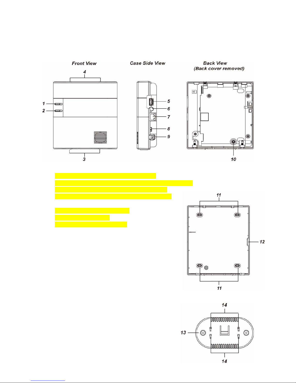
2.1. Identifying the parts:
1. LED 1 (Green/Red)
LED 1 Red On – Area 1 in the Full Arm mode.
LED 1 Red Flash– Area 1 in the Home 1/Home2/Home3 mode
LED 1 Green On – System in the learning mode.
LED 1 Green Flash – System in the Walk Test mode.
2. LED 2 (Red/Yellow)
LED 2 Red On –Alarm in Memory
LED 2 Red Flash– Alarm
LED 2 Yellow On – System Fault
3. Bottom Fixing Screw (x2)
4. Clasp Hook (x2)
5. USB Port
- Z-Wave dongle USB port
6. Reset/Learn Button
7. Ethernet Port
8. Battery Switch
9. DC Jack
- For connecting DC 9V 1A switching power.
10. Tamper Switch
11. Wall Mounting Knockouts (x4)
12. Wiring Hole
13. Bracket (for Desktop Deployment)
14. Bracket Hooks (for Desktop Deployment)

5
2.2. The Power Supply:
An AC power adapter is required to connect to a wall outlet. Be sure only to use an adapter with
the appropriate AC voltage rating to prevent component damage. DC 9V 1A switching power
output adaptor is generally used to power the Control Panel with 4.8V, 1100mAh Ni-mH
rechargeable battery pack and DC 12V 1A switching power is used to power the Control Panel
with 7.2V, 1600 mAh, Ni-mH rechargeable battery pack.
Rechargeable Battery
HSGW-X-4B series includes 4.8V, 1100 mAh, Ni-mH rechargeable battery pack or
HSGW-X-6B series includes 7.2V, 1600 mAh, Ni-mH rechargeable battery pack (required
for 3Gor 3G dongle option)
In addition to the adapter, there is a rechargeable battery inside the Control Panel, which
serves as a backup in case of a power failure.
During normal operation, the AC power adapter is used to supply power to the Control
Panel and at the same time recharge the battery. Slide the Battery Switch to ON to activate
and charge the battery. It takes approximately 72 hours to fully charge the battery
The battery status information is displayed in the Panel section of local area webpage.
2.3. System Requirements:
The system requires a TCP/IP network environment for you to connect to the Control Panel for
system programming.
Hardware requirement for programming the panel vial LAN webpage:
Microsoft Windows 98, ME, NT4.0, 2000, XP, Windows 7 or 8operating system.
Microsoft Internet Explorer 6.x, or later and Mozilla Firefox 3.0 compatible.
CD-ROM drive
CPU: Intel Pentium II 266MHz or above
Memory: 32MB (64MB recommended)
VGA resolution: 800x600 or above

6
3. Getting Started
Read this section of the manual to learn how to set up your Control Panel and program System
Settings over the Web page.
3.1. System Deployment
Follow guidelines below when planning installation location:
The Control Panel requires Ethernet connection.
The Control Panel should be installed at a location that is hidden from outside view.
Avoid mounting the Control Panel near large metal objects which may affect wireless radio
strength.
The Control Panel should be protected by sensors so that no intruder can reach the Control
Panel without first activating a sensor.
When using routers to improve network coverage, remember to use only Router
with backup batteries for security sensors. If you use a Router without backup battery for
security sensors, the Router will be powered down in case of AC failure, and you security
sensors will lose connection with the network.
Home Automation devices (Power Switches…etc) do not have this limit and can be used
with any Router.
3.2. Installation
The Control Panel can be placed on deskop.
1 The panel casing is secured by two top clasp hooks and two bottom screws and lossen the
2 bottom fixing screws and then two top clasp hooks to open cover.
2 Flip over the panel for configuration:
I. Connect Ethernet cable to panel Ethernet port.
II. Connect the Power Adaptor to a Wall Outlet and the other end to the Control Panel.
After several seconds, the Control Panel will emit 2 beeps to indicate that the system
is now operational.
III. Slide Battery Switch to ON position.
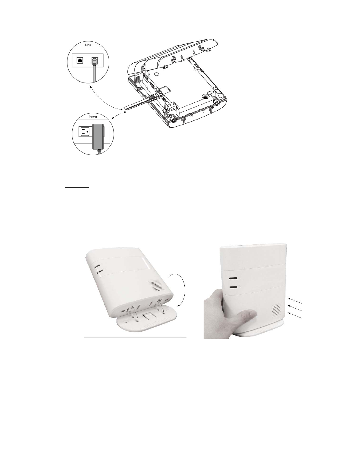
7
3 The back cover of the panel has one line hole for wiring purpose.
4 Choose to install the panel on desktop.
Desktop:
I. Replace the back cover, wire the cable through the side line hole and tighten the 2
fixing screws on the bottom.
II. Replace the standing base bracket.
III. Put the panel at desired location to finish installation.
Altri manuali per vesta series
1
Questo manuale è adatto per i seguenti modelli
15
Indice
Altri manuali Climax Technology Sistema di sicurezza


Manuali Sistema di sicurezza popolari di altre marche


EDM
EDM Solution 6+6 Wireless-AE Manuale utente

Highway Safety Group
Highway Safety Group EA401 Manuale utente

Siren
Siren LED GSM Manuale utente

Detection Systems
Detection Systems 7090i Istruzioni per il montaggio

Se-Kure Controls
Se-Kure Controls MicroMini SK-4841 Manuale utente

Siemens
Siemens FDM273 Manuale utente