cnsat Smart Antenna Selector Manuale utente


Index:
Chapter 1 - Introduction
Chapter 2 - Windows PC Application
2.1 – First Access
2.2 – Configuration
2.3 – Smart Antenna Selector Page
Chapter 3 - Ipad Crestron App

Chapter 1 - Introduction
The Smart Antenna Selector is equipped with a pre-installed graphical user interface, designed to
add lot of fucntions compared to the rack unit front panel.
There are two installed GUI. One is designed for Windows PC and allow the user to make changes
on basic configuration and manage the Smart Antenna Selector functions. The other one is designed
for Apple Ipad and allow the user to manage only the Smart Antenna Selector funtions, no
configuration can be changed from this GUI.
In both GUIs the user can find the same “buttons” of the rack unit front panel, plus some
informations about the antenna status. The values which can be viewed from both GUIs are:
Antennas A.C.U. ethernet link status, with visible IP address. 1
Antennas tracking status: with visible tracking satellite and status. 2
Antenna signal level: with visible AGC and S/N Ratio (for HD11, and TV Series) or BER
(for HD7 antennas).3
Antenna position: with visible azimuth relative and elevation
Antenna model: selected from user.
In the following chapters there's a guide of how to use both kind of GUIs.
1 The Smart Antenna Selector can take values from antenna control unit only
via TCP/IP link, so the ethernet link status in one of the most important parameters to observe.
2 The values of the tracking status are the same of the antenna web interface or A.C.U. display.
3 The model is a user selection only via Windows PC GUI. By selecting the model the system react automatically to
have the corrent informations shown. (S/N Ratio or BER).

Chapter 2 - Windows PC Application
2.1 – First Access
This GUI is the most complete way to manage and/or use the functions of the Smart Antenna
Selector.
The “brain” behind all the processes is a Crestron DIN-AP3 automation processor which carry
onboard a GUI made by the Crestron Xpanel technology.
This GUI allow you to:
Select the target IP addresses of both antennas ACU/TV Hub, to allow the processor to link
them and decode the data stream incoming.4
Configure the azimuth limits of both antennas, or better to set the “blind” sector.
Select the antennas models. 5
Configure the IP address, netmask and default gateway of the S.A.S. Itself
Select the operation mode, or better SMART (manual or automatic) and DIRECT.
The first installation is quite simple.
The S.A.S. is configured to have a default IP address of: 192.168.1.100
Open the folder with the Windows PC application inside (is an .exe file). The following page will
appear:
4 This means that the IP address of both ACUs/TV Hub has to be set before configuring the Smart Antenna Selector
target IP addresses.
5 The Smart Antenna Selector is available only for antennas with TCP/IP link, so the G and M series cannot be linked

In the upper menu you have to select “Options” and then “Settings”:
Now you have to digit the IP address of the S.A.S.
If is the default one just digit 192.168.1.100, otherwise use the current IP address.

2.2 – Configuration
If the S.A.S. Is correctly connected to a netwok (trough a ethernet switch and/or router) and you set
the correct IP address the following page will appear:
This is the “Home Page” where you can access the configuration page or the operational page.
If you click on “Configuration” the following page will appear:

In this case the “A Antenna” page is shown, the default one is empty, so you have to select one of
the options of the upper menu (green circle).
If you click on the home icon (red circle) you will be back to the Home Page.
The “A Antenna” and “B Antenna” are the same pages, with of course, different values. You have to
associate the “A” antenna and “B” antenna with the ones installed and remember this decision. In
fact when you have to configure the azimuth limits you need to know the position of the antenna
(stb or ptb side, or sometimes, fwd or aft) to set the correct angles. Same for the IP address of the
ACU.
If you want to change some values just click on “New” buttons (yellow circle) and use the cursors
to make your changes:
Once you set the value you want just click on “Submit” button (yellow cirlce).
In the “Model” section just click on the model button (green circle) to select the installed antenna
model.
Setting the azimuth limits values is very simple. Below you can find a simple schematic:

azimuth low limit
azimuth high limit
In this case both antennas are installed facing the FWD. In some cases one of the antennas is
installed facing the AFT. In this case adjust the angles following this consideration.
Just to give an example, in the previous schematic the values for Antenna A are around:
low limit : 30°
up limit : 150°
For Antenna B:
low limit : 210°
up limit : 330°
The values that you can insert are filtered by the logic and if you change something with a not
correct value the system will activate the flag “not valid” which can be found below the buttons
“New” and “Submit”. For example the azimuth limits are limited to 0° to 359° and the IP address
cannot go over 255.255.255.255. Inside the green circle you can find the Not Valid flag active and
the reason of the activation.
In this case a not valid IP address was been inserted (392.xxx.xxx.xxx).
ANTENNA A ANTENNA B
MAST
FWD=0°
FWD=0°
BLIND
SECTOR
BLIND
SECTOR
AFT=180° AFT=180°

Concerning the CPU Processor IP configuration is necessary to introduce something more. If you
click on “CPU Processor” page you will see the following subpage:
As you can see the addresses fields are empty. You can see only the current IP config (green circle).
This is due to the fact that if there's “something” on one of that strings, the CPU will set that values
to its ethernet board after a reboot.
So, if you need to change the IP address of the CPU (of course is the IP address of the S.A.S.
Itself), you have to be sure about the parameters to insert. If you set something wrong or an IP
which is no more reachable from your network, the only was to come back is to use the USB
interface and Crestron Toolbox.
To set new values for CPU, just click on “New” button of one ot the fields and wait until you can
see the blue cursor on the first number. After that use the cursor to change the values and at the end
click on “Submit” button. After clicking submit be absolutely sure that the values are correct and
click on “Apply”. This button reboot the system so the interface cannot be more used for around
five minutes.
After that time, open again the .exe file of the Windows PC GUI and replace the old IP address with
the one you set before. If you did everything correct you will see again the GUI. If not you need to
check your network and if you cannot find the S.A.S. you need support from a Crestron Technician
to restore a factory configuration.
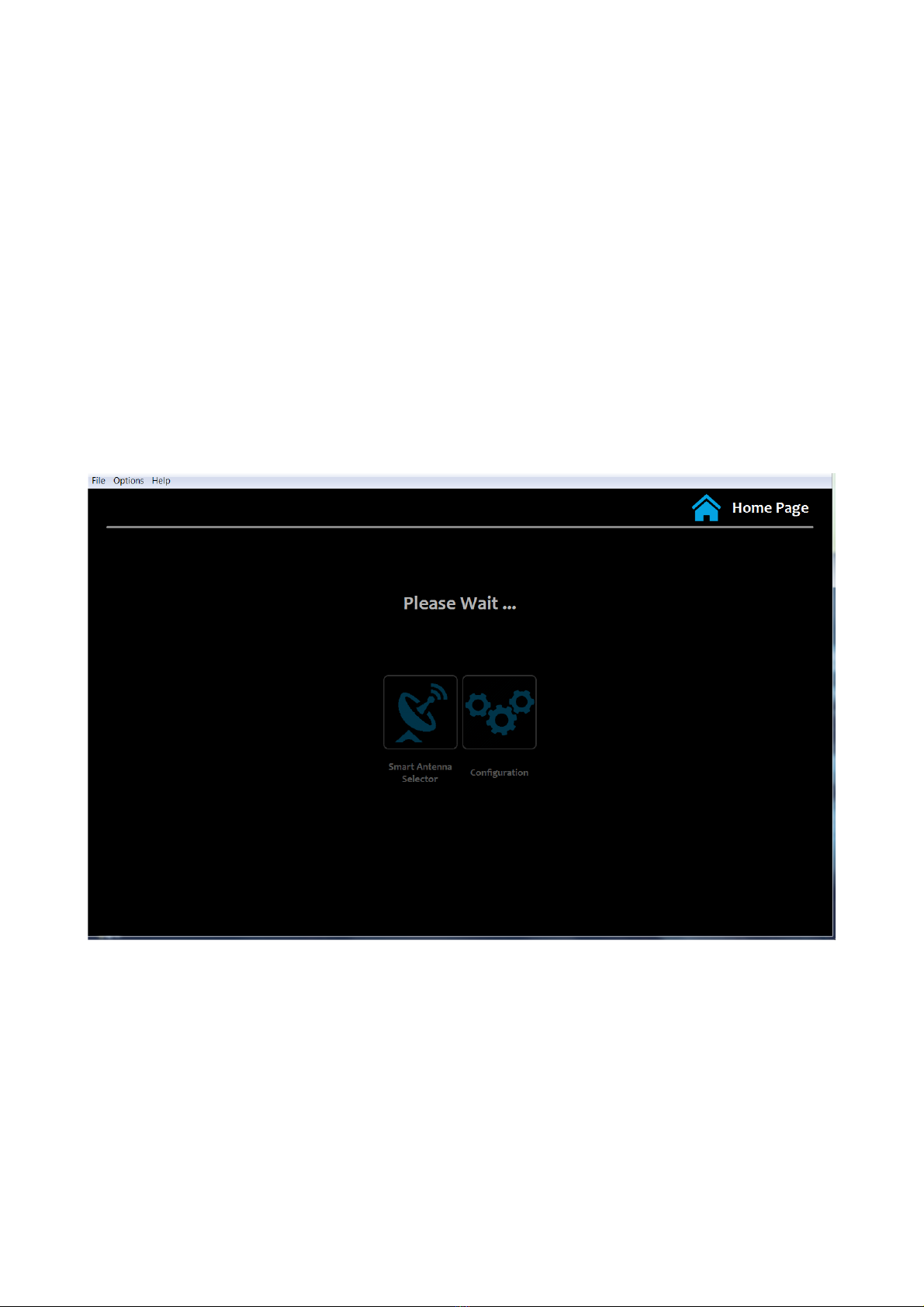
Once you open again the Windows PC GUI and the processor is still initializing you can see this
page:
After the wait time, which is around one minute you can access again the GUI.
Altri manuali per Smart Antenna Selector
1
Indice


