
Colby Instruments XT-100 Manuale del proprietario

XT-100
Operating and Programming Manual
Version 1.0

Certication and Warranty
Certication
Colby Instruments certies that the XT-100 programmable delay line instrument meets all published specications at the time the
instrument is shipped from the manufacturer. SPECIFICATIONS ARE SUBJECT TO CHANGE WITHOUT NOTIFICATION.
Warranty
The product is warranted against defects in material and workmanship for a period of one year from date of shipment. During
the warranty period, Colby Instruments will at its option, either repair or replace the product or item which proves to be defective.
Replacement products may be either new or like-new.
EXCESSIVE WEAR OF CONNECTORS, THE TROMBONE UNIT, THE COAXIAL RELAYS, AND OTHER RELAYS CARRYING THE SIGNAL, ARE
NOT COVERED BY THE WARRANTY. THE FOREGOING WARRANTY SHALL NOT APPLY TO DEFECTS RESULTING FROM IMPROPER CARE
OR USE OF THE INSTRUMENT BY THE BUYER. THIS SHALL APPLY TO ALL COMPONENTS DELIVERED TO THE BUYER.
For warranty service or repair, this product must be returned to Colby Instruments. The Buyer shall prepay all shipping charges for the
shipment of item to Colby Instruments. Colby Instruments shall pay the shipping charges to return the product to the Buyer. However, the
Buyer shall be responsible for ALL shipping charges, duties and taxes for product returned to Colby Instruments from outside the United
States of America.
BUYER MUST OBTAIN A RETURN MATERIAL AUTHORIZATION NUMBER (RMA #) FROM COLBY INSTRUMENTS PRIOR TO THE SHIPMENT
OF ANY ITEM TO COLBY INSTRUMENTS. SHIP TO:
Colby Instruments
Attn: RMA # ________
15375 SE 30th Place, Suite 320
Bellevue, Washington 98007
USA
No other warranty is expressed or implied. Colby Instruments specically disclaims the implied warranties or merchantability and tness
for a particular purpose. The remedies provided herein are the Buyer’s sole and exclusive remedies. Colby Instruments shall not be liable
for any direct or special, incidental or consequential damages, whether based on contract, tort, or any other legal theory.

iCOLBY INSTRUMENTS XT-100 VERSION 1.0 OPERATING AND PROGRAMMING MANUAL
XT-100 Technical Specications iii
XT-100 Trombone Measurements iv
S21 Insertion Return Loss Report iv
XT-100 Hostname and MAC-ID iv
Chapter 10 1
Description of the XT-100 programmable delay line instrument 1
1.1 Introduction . . . . . . . . . . . . . . . . . . . . . . . . . . . . . . . . . . . . . . . . . . . . . . . . . . . . . . . . . 1
1.2 Delay Line Structure and Design . . . . . . . . . . . . . . . . . . . . . . . . . . . . . . . . . . . . . . . . . . . . . . 1
Chapter 20 2
Getting Started 2
2.1 Using the XT-100 for the First Time . . . . . . . . . . . . . . . . . . . . . . . . . . . . . . . . . . . . . . . . . . . . 2
2.1.1 Connecting cables to the XT-100 . . . . . . . . . . . . . . . . . . . . . . . . . . . . . . . . . . . . . . . . . . 2
2.2 Self-Test After Power Up . . . . . . . . . . . . . . . . . . . . . . . . . . . . . . . . . . . . . . . . . . . . . . . . . . 3
Chapter 30 4
Using the Front Panel Connections 4
3.1 Overview of the Front Panel Connections . . . . . . . . . . . . . . . . . . . . . . . . . . . . . . . . . . . . . . . . . 4
3.2 Trombone Only Model XT-100-625P . . . . . . . . . . . . . . . . . . . . . . . . . . . . . . . . . . . . . . . . . . . . 4
3.3 Models XT-100-001N thru XT-100-100N . . . . . . . . . . . . . . . . . . . . . . . . . . . . . . . . . . . . . . . . . . 4
Chapter 40 5
Connecting to XT-100 to Set Delay 5
4.1 About the default IP address and DHCP . . . . . . . . . . . . . . . . . . . . . . . . . . . . . . . . . . . . . . . . . . 5
4.2 Working with Web Browser UI . . . . . . . . . . . . . . . . . . . . . . . . . . . . . . . . . . . . . . . . . . . . . . . 5
4.3 About the default Username and Password . . . . . . . . . . . . . . . . . . . . . . . . . . . . . . . . . . . . . . . . 5
4.4 About the XT-100 Web Server Control Page . . . . . . . . . . . . . . . . . . . . . . . . . . . . . . . . . . . . . . . . 6
4.5 About the XT-100 Web Server Information Page. . . . . . . . . . . . . . . . . . . . . . . . . . . . . . . . . . . . . .7
4.6 About the XT-100 Web Server Congure Page . . . . . . . . . . . . . . . . . . . . . . . . . . . . . . . . . . . . . . .8
4.7 Working via Remote Interfaces . . . . . . . . . . . . . . . . . . . . . . . . . . . . . . . . . . . . . . . . . . . . . . 9
4.8 Communicating over Ethernet TCP/IP . . . . . . . . . . . . . . . . . . . . . . . . . . . . . . . . . . . . . . . . . . .9
4.9 Default Network Addresses. . . . . . . . . . . . . . . . . . . . . . . . . . . . . . . . . . . . . . . . . . . . . . . . .9
4.10 Restoring to Factory Default Settings. . . . . . . . . . . . . . . . . . . . . . . . . . . . . . . . . . . . . . . . . . .9
4.11 About Connecting via Telnet to the XT-100 . . . . . . . . . . . . . . . . . . . . . . . . . . . . . . . . . . . . . . . 10
4.12 Setting the delay over RS-232 Serial Port and PC . . . . . . . . . . . . . . . . . . . . . . . . . . . . . . . . . . . 10

ii COLBY INSTRUMENTS XT-100 VERSION 1.0 OPERATING AND PROGRAMMING MANUAL
4.13 Attaching the MT-100A Microterminal to the RS-232 port . . . . . . . . . . . . . . . . . . . . . . . . . . . . . . . 11
4.14 Attaching the PC to the RS-232 port . . . . . . . . . . . . . . . . . . . . . . . . . . . . . . . . . . . . . . . . . . 11
4.15 Using HyperTerminal and RS-232 connection . . . . . . . . . . . . . . . . . . . . . . . . . . . . . . . . . . . . . 12
Chapter 50 13
Programming the XT-100 13
5.1 About Programming the XT-100 . . . . . . . . . . . . . . . . . . . . . . . . . . . . . . . . . . . . . . . . . . . . . 13
5.1.1 Instrument ID. . . . . . . . . . . . . . . . . . . . . . . . . . . . . . . . . . . . . . . . . . . . . . . . . . . . 13
5.1.2 Setting the Delay using del1 or del2 commands . . . . . . . . . . . . . . . . . . . . . . . . . . . . . . . . . 13
5.1.3 Querying the current delay setting . . . . . . . . . . . . . . . . . . . . . . . . . . . . . . . . . . . . . . . . 13
5.1.4 Setting the delay using a numeric value only. . . . . . . . . . . . . . . . . . . . . . . . . . . . . . . . . . . 13
5.1.5 Determine if the operation has completed . . . . . . . . . . . . . . . . . . . . . . . . . . . . . . . . . . . . 14
5.1.6 Check the error code. . . . . . . . . . . . . . . . . . . . . . . . . . . . . . . . . . . . . . . . . . . . . . . . 14
5.1.7 Determine the network address and settings . . . . . . . . . . . . . . . . . . . . . . . . . . . . . . . . . . 14
5.1.8 About the MODE command and MODE? query. . . . . . . . . . . . . . . . . . . . . . . . . . . . . . . . . . 14
5.1.9 Setting a STEP size and using the INC and DEC commands . . . . . . . . . . . . . . . . . . . . . . . . . . 14
5.2 About Trombone Calibration . . . . . . . . . . . . . . . . . . . . . . . . . . . . . . . . . . . . . . . . . . . . . . . 15
5.2.1 Enable Calibration Table. . . . . . . . . . . . . . . . . . . . . . . . . . . . . . . . . . . . . . . . . . . . . . 15
5.2.2 Displaying information about the Calibration Table . . . . . . . . . . . . . . . . . . . . . . . . . . . . . . . 15
5.2.3 Setting Calibration Table entries . . . . . . . . . . . . . . . . . . . . . . . . . . . . . . . . . . . . . . . . . 15
5.2.4 Using the Calibration Table . . . . . . . . . . . . . . . . . . . . . . . . . . . . . . . . . . . . . . . . . . . . 15
5.3 About Relays in the XT-100 . . . . . . . . . . . . . . . . . . . . . . . . . . . . . . . . . . . . . . . . . . . . . . . . 16
5.4 About Trombone Serial or Parallel Operating Mode . . . . . . . . . . . . . . . . . . . . . . . . . . . . . . . . . . . 16
Chapter 60 17
Application Programming Interfaces (API) and Commands 17
6.1 Setting Delay Commands and Queries . . . . . . . . . . . . . . . . . . . . . . . . . . . . . . . . . . . . . . . . . . 19
6.2 System Commands . . . . . . . . . . . . . . . . . . . . . . . . . . . . . . . . . . . . . . . . . . . . . . . . . . . . 20
6.3 Calibration Table Commands and Queries . . . . . . . . . . . . . . . . . . . . . . . . . . . . . . . . . . . . . . . . 22
6.4 Networking Settings. . . . . . . . . . . . . . . . . . . . . . . . . . . . . . . . . . . . . . . . . . . . . . . . . . . . 24
6.5 Common Commands . . . . . . . . . . . . . . . . . . . . . . . . . . . . . . . . . . . . . . . . . . . . . . . . . . . 26
6.6 Relay commands for Models XT-100-001N thru XT-100-100N . . . . . . . . . . . . . . . . . . . . . . . . . . . . . 28
Chapter 70 29
Instrument Backpanel 29

iii COLBY INSTRUMENTS XT-100 VERSION 1.0 OPERATING AND PROGRAMMING MANUAL
XT-100 Technical Specications
Model XT-100
Serial Number 21090000
Firmware Version 1.00
Channel 1 625.0 ps
Signal Input Range 0 - 18 GHz
Minimum Step Resolution 0.25 ps
Maximum Delay Range 625 ps, 2.50 ns, 5.00 ns, 10.0 ns, 20.0 ns, 50.0 ns, 80.0 ns, 100.0 ns
Nominal Delay 3.30 ns
Accuracy of Delay +/- 0.12 ps σ = 0.05
S21 Typical Insertion Loss
1.0 dB + 1.0 dB x f[GHz] for 0 to 2.0 GHz
3.0 dB + 0.8 dB x f[GHz – 2.0] for 2 to 4.5 GHz
6.6 dB + 0.8 dB x f[GHz – 4.5] for 4.5 to 18.0 GHz
S11 Typical Return Loss
15 dB to 1 GHz
10 dB to 3 GHz
8 dB to 4.5 GHz
Phase Shift Step Resolution 0.18 ° per 1 GHz
Total Phase Shift at 1 GHz 225°, 900°, 1800°, 3600°, 7200°, 18000°, 28800°, 36000°
Total Phase Shift at 5 GHz 1125°, 4500°, 9000°, 18000°, 36000°, 90000°, 144000°, 180000°
Switching Speed* 250 ms – 6500 ms
External Trigger no
Ethernet TCP/IP yes
Serial RS-232 yes
MT-100A optional
Web Browser UI yes
Microwave Relays Rated 5m MTBF
Recommended Service Interval 500,000 operations or 1 year
Min frequency for 360° phase shift coverage 1.6 GHz, 400 MHz, 200 MHz, 100 MHz, 50 MHz, 20 MHz, 12.5 MHz, 10 MHZ
Power Handling Capability
10W CW, 50W peak
*Operating at sustained high power levels while changing delay settings or “hot
switching” will signicantly reduce operational lifetime of instrument.
AC Supply 85 to 240 VAC, 50-60 Hz
Operating Temperature 10 to 30 deg. C
Physical Dimensions 12" L x 16 3/4" W x 3 1/2" H (2U)
Weight 4.1 kg (9.0 lbs.) to 5.0 kg (11 lbs.)
*depending on network latency

iv COLBY INSTRUMENTS XT-100 VERSION 1.0 OPERATING AND PROGRAMMING MANUAL
XT-100 Trombone Measurements
XT-100 Hostname and MAC-ID
Hostname COLBY_21090000
MAC-ID 00:00:00:00:00:00
S21 Insertion Return Loss Report

Chapter 10
Description of the XT-100 programmable delay line instrument
11 Introduction
The XT-100 Programmable Delay Line Instrument offers precision programmable delay from 0 to 625.0 picoseconds (ps) range with a
step resolution precision to 0.50 ps per step and wideband signal frequency input from DC to 18 GHz.
The XT-100 offers electrical delay (or phase shift) through a patented electromechanical trombone unit by varying the total signal path
length. Movement is controlled by a high precision aerospace-grade hybrid stepper motor. Step resolution is to 0.50 ps per step with
excellent repeatability.
The XT-100 can be operated locally via Web Browser UI over an Ethernet interface or optionally via MT-100A MicroTerminal over a RS-232
serial port interface. Delay can be set or entered manually or automated via program control. Remote control via Ethernet TCP/IP, RS-
232 Serial interface, or Web Browser UI and SCPI command interface is supported.
All signal input and output connections are easily accessible at the front panel and are terminated with female SMA (50 Ω) connectors.
12 Delay Line Structure and Design
The XT Series of Programmable Delay Line Instruments is based on an “electromechanical trombone” or moveable delay line. A high-
frequency signal passing through an extended or contracted trombone experiences correspondingly more or less electrical delay due to
the varying total signal path-length. The electrical delay corresponds directly to phase shift when measured in the frequency domain.
A digital hybrid precision stepper motor with a custom precision lead screw is used to position a sled on which one part of the trombone
tubing is attached. Precision interfaces are designed to minimize impedance mismatches and a proprietary contact design achieves
reliability while minimizing any signal loss or noise.
An embedded CPU microcontroller processes commands from any of the attached hardware interfaces: Ethernet (Web Browser UI, TCP/
IP) or RS-232 Serial (optional MT-100A MicroTerminal, or Terminal Emulator program). Commands are processed to move the stepper
motor in high-resolution step increments as ne as 0.50 picoseconds(ps) of step resolution (or 0.18 degrees per 1 GHz signal input).
The model XT-100 has one trombone in the base unit. Total delay range can be extended by the in-series addition of one or more delay
sections. Each delay section is a pair of aerospace grade microwave relay switches and precision cut semi-rigid coaxial cable in binary
step size lengths corresponding to multiples of 625.0 ps. e.g., 625 ps, 1.25 ns, 2.50 ns, etc. Total range of delay is the sum of the entire
path length of each of the delay sections. With the combination of binary step sized delay sections and the electromechanical trombone,
any 0.50 ps step can be achieved from 0 to total range of the instrument.
1COLBY INSTRUMENTS XT-100 VERSION 1.0 OPERATING AND PROGRAMMING MANUAL

Chapter 20
Getting Started
21 Using the XT-100 for the First Time
After unpacking the instrument, carefully inspect it for any shipping damage. Remove all standard accessories from the shipping carton.
Model XT-100 back panel
211 Connecting cables to the XT-100
1. Plug in the XT-100 to a power source by inserting the AC power cord into the 85 to 240 VAC power entry
module located on the back panel.
2. If you have an RJ-45 Ethernet cable, connect the cable into the Ethernet Port connector.
3. If you have the (optional) MT-100A MicroTerminal, connect the mated cable to the XT-100 and to the
MT-100A MicroTerminal.
3 Insert MT-100A DB-9 cable (optional)
2 Insert Ethernet cable
1 Insert the AC Power Cord
2COLBY INSTRUMENTS XT-100 VERSION 1.0 OPERATING AND PROGRAMMING MANUAL

212 Turning power ON to the XT-100
Model XT-100 front panel
Model XT-100 with extended range delay sections
*Push the at rocker switch on the front panel to turn on the XT-100 System Unit.
22 Self-Test After Power Up
The XT-100 utilizes an embedded microprocessor to perform all necessary tasks. Upon power-up, the XT-100 will initialize and perform
an initial self-test.
The XT-100 will now check the calibration of the trombone channel by moving the electromechanical trombone delay line towards its
maximum setting (maximum delay) until it reaches an infrared light barrier set at a precise position.
A full-speed test is then performed by moving the delay back to 0 relative (minimum delay) and then back to 625.0 ps and re-checking
the calibration setting.
If microwave relays are installed, a power cycle to OFF, ON, and then back to the OFF position of all the installed relays will be performed.
The delay is reset to its zero delay (0.0 ps) position and the unit is ready to accept commands.
3COLBY INSTRUMENTS XT-100 VERSION 1.0 OPERATING AND PROGRAMMING MANUAL
Chapter 30
Using the Front Panel Connections
31 Overview of the Front Panel Connections
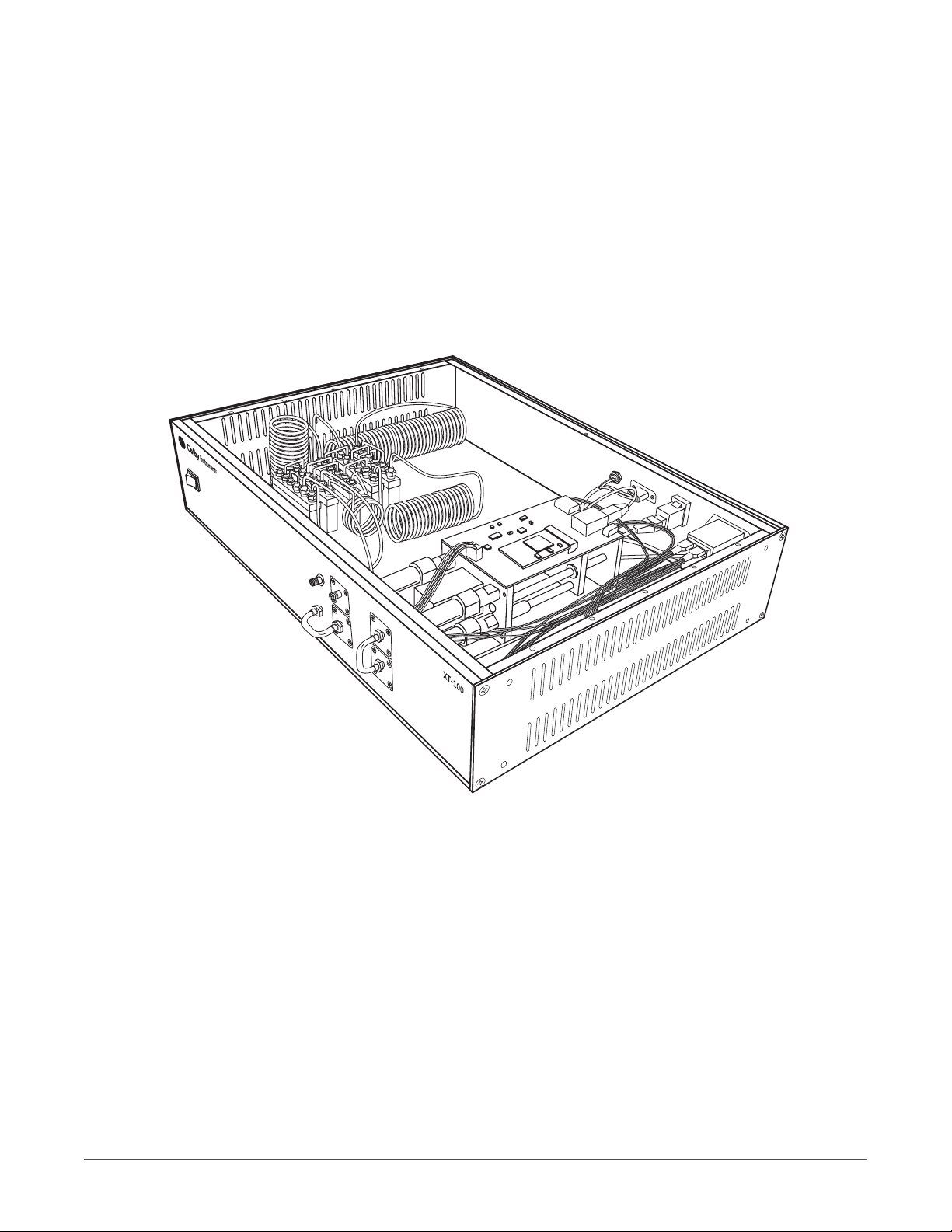
The Trombone IN connector begins the signal path and continues through the internal top half of the electromechanical trombone and
out across the vertical jumper and back through the bottom half of the trombone and exiting at the OUT connector.
Model XT-100 single trombone
32 Trombone Only Model XT-100-625P
The total delay range is from 0 to 625.0 ps offered through both halves of the trombone. The hybrid stepper motor offers 0.50 ps
step resolution.
33 Models XT-100-001N thru XT-100-100N
Total delay is offered through the electromechanical trombone and delays sections.
4COLBY INSTRUMENTS XT-100 VERSION 1.0 OPERATING AND PROGRAMMING MANUAL
Questo manuale è adatto per i seguenti modelli
1
Indice
Altri manuali Colby Instruments Generatore di impulsi


