Comfee CVP30W7AST Manuale utente

version A - 11 - 2021
USER MANUAL
en
Range Hood
Power supply: 120V
Rated power: 323W
Frequency: 60Hz
Free 3 months
extension of the
original limited warranty
period!* Simply text a
picture of your proof of
purchase to:
1-844-224-1614
*The warranty extension is for the
three months immediately following
the completion of the product’s
original warranty period.
MODEL NUMBER CVP30W7AST
CVP36W7AST


WARNING alerts you to situations that may
cause serious body harm, death or property
damage.
INTENDED FOR RESIDENTIAL COOKING USE ONLY
READ ALL INSTRUCTIONS BEFORE INSTALLATION AND USE
WARNING CAUTION IMPORTANT
IMPORTANT indicates installation, operation,
maintenance or valuable information that is not
hazard related.
TO REDUCE THE RISK OF FIRE, ELECTRIC SHOCK
OR INJURY TO PERSONS, OBSERVE THE
FOLLOWING:
1. Use this unit only in the manner intended by the manufacturer. If
you have questions, contact the manufacturer at the address or
telephone number listed in the warranty.
2. Before servicing or cleaning unit, unplug and switch power off at
service panel and lock service disconnecting means to
prevent power from being switched on accidentally. When the
service disconnecting means cannot be locked, securely fasten
a prominent warning device, such as a tag, to the service panel.
3. Installation work and electrical wiring must be done by
qualified personnel in accordance with all applicable codes and
standards, including fire-rated construction codes and
standards.
4. Sufficient air is needed for proper combustion and exhausting of
gases through the flue (chimney) of fuel burning equipment to
prevent backdrafting. Follow the heating equipment
manufacturer’s guidelines and safety standards such as
those published by the National Fire Protection Association
(NFPA) and the American Society for Heating, Refrigeration and
Air Conditioning Engineers
(ASHRAE) and the local code authorities.
5. When cutting or drilling into wall or ceiling, do not damage
electrical wiring and other hidden utilities.
6. Ducted fans must always be vented to the outdoors.
7. Do not use this unit with any solid-state speed control device.
8. TO REDUCE THE RISK OF FIRE , USE ONLY METAL
DUCTWORK.
9. This unit must be grounded. This appliance is equipped with a cord
having a grounding wire with a grounding plug. The plug must be
plugged into an outlet that is properly installed and grounded.
10. Do not use an extension cord. If the power supply cord is too short,
have a qualified electrician install an outlet near the appliance.
11. When applicable local regulations comprise more restrictive
installation and/or certification requirements, the aforementioned
requirements prevail on those of this document and the installer
agrees to conform to these at his own expense.
TO REDUCE THE RISK OF A RANGE TOP GREASE FIRE:
a) Never leave surface units unattended at high settings. Boilovers
cause smoking and greasy spillovers that may ignite. Heat oils
slowly on low or medium settings.
b) Always turn hood ON when cooking at high heat or when
flambeing food (i.e.: Crêpes Suzette, Cherries Jubilee,
Peppercorn Beef Flambé).
c) Clean ventilating fans frequently. Grease should not be allowed to
accumulate on fan, filters or in exhaust ducts.
d) Use proper pan size. Always use cookware appropriate for the
size of the surface element.
1. For indoor use only.
2. For general ventilating use only. Do not use to exhaust
hazardous or explosive materials and vapors.
3. To avoid motor bearing damage and noisy and/or unbalanced impeller,
keep drywall spray, construction dust, etc. off power unit.
4. Install the vent hood in a location away from strong drafts, such as
windows, door, and strong HVAC vent for best performance
5. The minimum hood distance above cooktop must not be less than
25-5/8". For best capture of cooking impurities, the bottom of the hood
should be at a maximum of 29-1/2" above cooking surface.
6. Two installers are recommended because of the large size and weight
of this unit.
7. To reduce the risk of fire and to properly exhaust air, be sure to duct air
outside — Do not exhaust air into spaces within walls or ceiling or into
attics, crawl space or garage.
8. Because of the high exhausting capacity of this unit, you should make
sure enough air is entering the house to replace exhausted air by
opening a window close to or in the kitchen.
9. Always leave safety grills and filters in place. Without these
components, operating blowers could catch onto hair, fingers and loose
clothing.
10. The vent hood and filters should be cleaned frequently.
WARNING WARNING
TO REDUCE THE RISK OF INJURY TO PERSONS IN
THE EVENT OF A RANGE TOP GREASE FIRE,
OBSERVE THE FOLLOWING*:
1. SMOTHER FLAMES with a close-fitting lid, cookie sheet or metal
tray, then turn off the burner. BE CAREFUL TO PREVENT BURNS. IF
THE FLAMES DO NOT GO OUT IMMEDIATELY, EVACUATE AND
CALL THE FIRE DEPARTMENT.
2. NEVER PICK UP A FLAMING PAN — You may be burned.
3. DO NOT USE WATER, including wet dishcloths or towels —This
could cause a violent steam explosion.
4. Use an extinguisher ONLY if:
A. You own a Class ABC extinguisher and you know how to
operate it.
B. The fire is small and contained in the area where it started.
C. The fire department has been called.
D. You can fight the fire with your back to an exit.
5. Based on “Kitchen Fire Safety Tips” published by NFPA.
CAUTION
SAVE THESE INSTURCTIONS
CAUTION indicates a potentially hazardous
situation which, if not avoided, may result in
minor or moderate injury.
1

)
COMPONENTS
Ref. Qty. Product Components
1 1 Hood Body, complete with: Controls, Light,
Blower, Filter.
2.1 1 Lower Decorative Chimney
2.2 1 Upper Decorative Chimney
3 2
2
3
Qty. Documentation
1 Instruction Manual
10
11
7
20
Screws M5 x 1.97''
Hood fixing bracket
7 Wall Plugs
12
21
6Screws M4.2 x 0.37''
1
1 Chimney fixing bracket
Ref. Qty. Optional Installation Components
2.2
2.1
3
1
20 12 11
21 10
The Activated Charcoal filter (optional)
Grease filter (30'')
Grease filter (36'')
4
4
2

A
9.0''
10.55''
18.58"
10.55"
6.73"
25.6''-29.53''
3
A
CVP30W7AST
CVP36W7AST
30"
35.4"

INSTALLATION PREPARATION
1. SELECT INSTALLATION TYPE
A. Vented Installation
B. Non-Vented / Recirculation Installation
Roof Discharge
This canopy hood is designed for venting through the roof or wall.
A 6" round vent system is needed for installation (not included). The hood
exhaust opening is 6" round.
Vent system can terminate either through the roof or wall.
To vent through a wall, a 90° elbow is needed.
Rear Discharge
A 90° elbow may be installed immediately above the hood.
If it is not possible to vent cooking fumes and vapors to the outside, the hood
can be used in the non-vented (recirculating) version, fitting a charcoal filter
and the deflector (not included, you can decide whether to use according to
your installation environment). Fumes and vapors are recycled through the top
grille. Non-Vented (Recirculating)
Wall VentingRoof Venting
A
A
B
B
B
A
A. Deflector
B. 6" round vent
A. Wall cap
B. 6" round vent
A. Roof cap
B. 6 round vent
Local building codes may require the use of makeup air systems when using ventilation
systems greater than specified CFM of air movement. The specified CFM varies from locale
to locale. Consult your HVAC professional for specific requirements in your area.
A. Vented Installation
WARNING
TO REDUCE THE RISK OF FIRE, USE ONLY METAL DUCTWORK.
4

8.5"
6.5"
2" min.
Centerline
Side
cabinet Side
cabinet
Vent and power
supply cable
entry location
20" min.
30" or 36"
Cooking surface
8.5"
■Vent system must terminate to the outdoors except for non-vented (recirculating)
installations.
■Do not terminate the vent system in an attic or other enclosed area.
■Do not use 4" laundry-type wall cap (plastic). Only use a metal exterior
exhaust vent.
■Use metal vent only. Rigid metal vent is recommended for best performane.
■All vent joints should be taped and sealed with 2"metal foil tape
■The length of vent system and number of elbows should be kept to a minimum to
provide efficient performance.
For the Most Efficient and Quiet Operation:
■Use no more than three 90° elbows.
■Make sure there is a minimum of 24" of straight vent between the elbows if
more than 1 elbow is used.
■Do not install 2 elbows together.
■Use clamps to seal all joints in the vent system.
■
■
Use caulking to seal exterior wall or roof opening around the cap.
The size of the vent should be uniform.
CAUTION
Vents and electrical should
be installed in the gray
shaded areas to provide a
clean finished look
INSTALLATION PREPARATION
25.6''-29.53''
5

INSTALLATION
Hood Mounting Screw Installation
1. Determine and mark the centerline on the wall where the hood will be installed.
2. Select a mounting height between a minimum of 25.6'' and a
suggested maximum of 29.53'' above the range to the bottom of the hood.
Mark a reference line on the wall.
3. Tape template in place, aligning the template centerline and bottom of template
with hood bottom line and with the centerline marked on the wall.
NOTE:Ensure that horizontal lines are level prior to marking hole locations.
Mark the hole location
with in 0.375" to 0.5"
of the ceiling or the
upper most hole
location.
Centerline of
cabinets
and/or cooktop.
Tape
25.6'' min to cooking surface
29.53'' max to cooking surface
Overlap the holes
when install the
adjustable
decorative
chimney.
13.38"
6

INSTALLATION
WALL DRILLING AND BRACKET FIXING
A vertical line up to the ceiling or up to the upper limit, at the center of the area in which the
hood is to be fitted.
A horizontal line C at a X
A horizontal line B at
A horizontal line A at a
B.
to the vertical reference line.
Repeat this operation on the other side and on the vertical reference line , checking that
the three marks are leveled.
to the vertical reference line.
Repeat this operation on the other side , checking that the two marks are leveled.
Mark a point (1) on the horizontal line B,
Mark a point (2) on the horizontal line C,
Mark a point (3) on the horizontal line A, to the vertical reference line.
Repeat this operation on the other side , checking that the two marks are leveled.
above the cooker top.
inch above the horizontal line
C
B(1)
A (3)
Vertical reference line
X
7.48" below the horizontal line
1.57"
6.69"
36.61" - 40.55"
7.48"
B.
3.15''
1.57"
3.15" 3.15"
6.69"
unit:inch
36.61" - 40.55"
1.57''
6.69''
Chimney X
/
15.75"+11.81'' 15.35''-24.41''
15.75"
Fix the brackets :
3/8'' drill bit.
Drill holes at the marked points with a
Insert the Wall Plugs 11 into the holes.
Fix the hood fixing bracket 20 with 3 screws 10 (0.2'' x 1.97'') at the horizontal line B.
Fix a Chimney fixing bracket 21 with 2 screws 10 (0.2'' x 1.97'') at the horizontal line C.
7
Assemble the Lower Chimney Cover:
•
•
Slide the Lower Decorative Chimney trim (2.1)
over the fan body.
Ensure that the Decorative trim is pressed
down to line up the lower mounting holes (A)
Slightly lift the Upper Decorative Chimney
cover
Insert 2 short sheet metal screws (12) in the
lower holes
•Place Chimney mounting bracket (21) at the top
of the Lower Decorative Chimney (2.1), and
insert 2 short sheet metal screws (12) into the
outer most holes on the bracket at location B
Pre-Assemble the Upper Chimney Cover :
•Remove the protective foil from the Upper
Decorative Chimney (2.2)
•Slide the Upper Decorative Chimney trim (2.2)
into the Lower Decorative Chimney trim
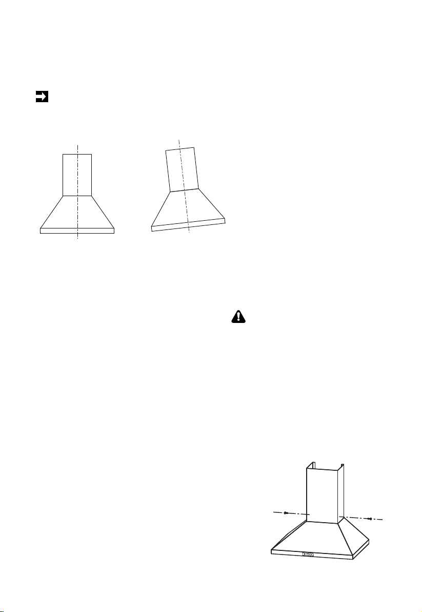
Hang and Mount the Vent Hood:
•Hang the vent hood onto fixing bracket 20
•Level the hood, and insert 2 long screws (10 )
into bracket 21 at level B
•Insert 2 long screws (10) into the hood at level A
Install Duct and Insert Plug:
•Install 6" duct over the flange on the fan body
•Use 2" wide metal tape to make an air tight
seal between the duct and the fan body
•Install a clamp to secure the ductwork
securely
•Remove Carbon Filters if installed
•Insert the plug into a properly grounded outlet
IMPORTANT
•The vent hood should be lifted and
installed by 2 people to prevent injuries
and potential damage
WARNING
Electrical Shock Hazard
•This unit must be grounded. This
appliance is equipped with a cord
having a grounding wire with a
grounding plug. The plug must be
plugged into an outlet that is
properly installed and grounded.
•Do not use an extension cord. If the
power supply cord is too short,
have a qualified electrician install
an outlet near the appliance.
Right Wrong
2.1
12
•
•
8
Questo manuale è adatto per i seguenti modelli
1
Indice
Altri manuali Comfee Cappa di ventilazione


