COMFILE CUPC-P200 Series Manuale utente

CUPC-P200 Series
User Manual
(P200, P220)
[Version 1.0]
COMFILE Technology Inc.
www.comfiletech.com

CUPC P200 Series User Manual
2/27
1175 Chess Dr., Suite F, Foster city, CA 94404, USA www.comfiletech.com
Table of Contents
Chapter 1. Hardware Specification ...................................................................................... 3
Chapter 2. External Parts .................................................................................................... 4
Chapter 3. Dimensions ......................................................................................................... 5
3-1. CUPC-P200 Dimensions............................................................................................. 5
3-2. CUPC-P220 Dimensions............................................................................................. 6
Chapter4. PANEL CUTOUT................................................................................................. 7
4-1 Installation Requirements and Installation.......................................................... 7
Chapter 5. Bracket Installation ............................................................................................ 8
5-1. CUPC-P200 Bracket Installation.................................................................................. 8
5-2. CUPC-P220 Bracket Installation.................................................................................. 9
Chapter 6. Input/Output Connectors .................................................................................. 10
6-1. VGA Output Connector............................................................................................... 10
6-2. RS232C Input/Output Connector (COM1, COM2, COM3)................................................. 10
6-3. Power Input Connector ......................................................................................... 11
Chapter 7. System Restoration .......................................................................................... 12
7-1. Getting Ready .......................................................................................................... 12
7-2. ROM Bios Configuration ....................................................................................... 13
7-2-1. Changing First Boot Device ............................................................................... 13
7-3. Booting with the WinClon SDCARD ........................................................................ 15
7-4. Restoration.......................................................................................................... 16
7-5. Backing Up ........................................................................................................... 21
MEMO ................................................................................................................................. 27

CUPC P200 Series User Manual
3/27
1175 Chess Dr., Suite F, Foster city, CA 94404, USA www.comfiletech.com
Chapter 1. Hardware Specification
Model name
Item CUPC-P200 CUPC-P220
CPU Intel ATOM N270 1.6GHz
Chipset Intel 945GSE + ICH7M
Memory 2GB SODIMM DDR2 SDRAM
Graphic & Display Intel 945GSE Embedded Graphics
Support VGA CRT output
Support Pivot
LCD 15inch
16.7M Colors,
XGA(1024x768), 300cd/m2
10.4inch
262K Colors,
XGA(1024x768), 300cd/m2
Backlight 2Channel CCFL
LT : >50,000hr 1Channel CCFL
LT : >30,000hr
Ethernet VIA VT6130 Gigabit Ethernet(2Port)
Audio VIA High Definition Audio
Audio Out (1Port)
MIC In (1Port)
USB Universal Serial Bus Support (4Port)
Support USB2.0 Host Controller
HDD SATA HDD Interface
Serial RS232C Serial (2Port)
Input Power DC+12V
Power Consumption <32W (2.6A@12V) <28W (2.3A@12V)
Dimension(mm) 376(H) x 300(V) x 60(D) 280(H) x 300(V) x 60(D)
Weight 5.1Kg 2.5Kg
Operating Temperature 0℃~ 60℃
[Table 1] CUPC Hardware Specification

CUPC P200 Series User Manual
4/27
1175 Chess Dr., Suite F, Foster city, CA 94404, USA www.comfiletech.com
Chapter 2. External Parts
Name Description
A Power/HDD LED The green LED is turned on, when the power is supplied.
The red LED is turned on, when the hard disk is read or written.
B ATX Power S/W ATX mode power switch. Boot or exit the system.
C Ext. Power S/W The connector which can be linked to external switch. Same function with
ATX Power switch
D Power S/W Power input ON/OFF
E DC IN ø2.5 Adaptor Input Connector (DC +12V)
F USB Port USB1/USB2 (USB2.0)
G VGA Port VGA output for external monitor.
H Audio Out Sound output for external speaker
I MIC IN Microphone input
J LAN2 Port Support 100BaseT, with RJ-45 type connector
K LAN1 Port Support 100BaseT, with RJ-45 type connector
L USB Port USB3/USB4 (USB2.0)
M COM1 Port COM1 (RS232C, D-SUB 9Pin Male Type)
N COM2 Port COM2 (RS232C, D-SUB 9Pin Male Type)

CUPC P200 Series User Manual
5/27
1175 Chess Dr., Suite F, Foster city, CA 94404, USA www.comfiletech.com
Chapter 3. Dimensions
3-1. CUPC-P200 Dimensions
[Figure 1] CUPC-P200 Dimensions
Avoid using long bolts when
assembling VESA mounts or add-on
board.
The inner maximum length is about
12mm.
Back cover of
product

CUPC P200 Series User Manual
6/27
1175 Chess Dr., Suite F, Foster city, CA 94404, USA www.comfiletech.com
3-2. CUPC-P220 Dimensions
[Figure 2] CUPC-P220 Dimensions
Avoid using long bolts when assembling
VESA mounts or add-on board.
The inner maximum length is about
10mm.
Back cover of
p
roduct

CUPC P200 Series User Manual
7/27
1175 Chess Dr., Suite F, Foster city, CA 94404, USA www.comfiletech.com
Chapter4. PANEL CUTOUT
4-1 Installation Requirements and Installation
[Installation Requirements]
[Installation]
CUPC X (Width) Y (Height) T (Thickness) Unit
P200 355
[13.98]
279
[10.99]
1.6 to 12.0
[0.06 to 0.47]
mm
[inch]
P220 263
[10.36]
210
[8.27]
1.6 to 6.0
[0.06 to 0.24]
mm
[inch]

CUPC P200 Series User Manual
8/27
1175 Chess Dr., Suite F, Foster city, CA 94404, USA www.comfiletech.com
Chapter 5. Bracket Installation
5-1. CUPC-P200 Bracket Installation
To fasten CUPC-P200 to an upright panel, the brackets (left, right) are supplied when you purchase
P200.
* Procedure *
1) Push and install the CUPC-P200 into your panel.
2) Press the bracket as the following directions in two steps.
3) To fix the CUPC-P200 to the panel, fasten the bolts.

CUPC P200 Series User Manual
9/27
1175 Chess Dr., Suite F, Foster city, CA 94404, USA www.comfiletech.com
5-2. CUPC-P220 Bracket Installation
To fasten CUPC-P220 to an upright panel, the brackets (left 2ea, right 2ea) are supplied when you
purchase P220.
* Procedure *
1) Push and install the CUPC-P220 into your panel.
2) Press the bracket as the following directions in two steps.
3) To fix the CUPC-P220 to the panel, fasten the bolts.
CUPC P200 Series User Manual
10/27
1175 Chess Dr., Suite F, Foster city, CA 94404, USA www.comfiletech.com
Chapter 6. Input/Output Connectors
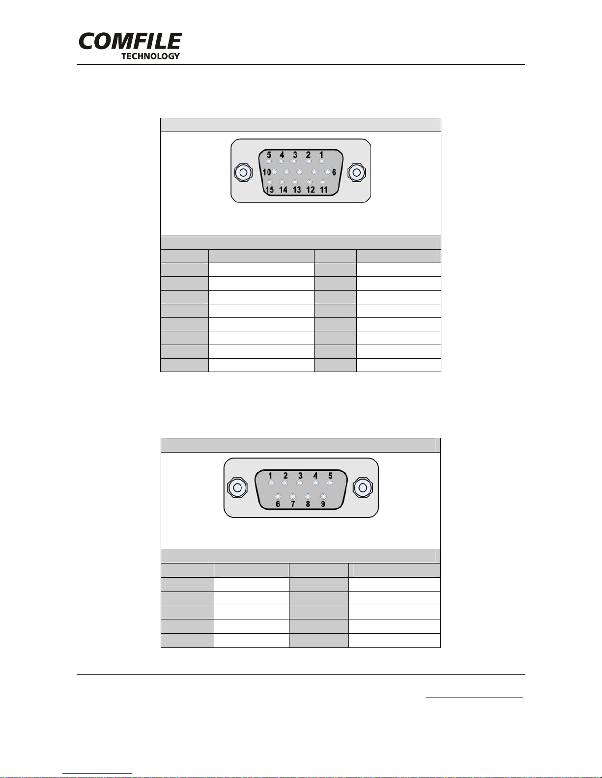
6-1. VGA Output Connector
Connector Type
* D-SUB 15Pin Female
Pin Assignment
Pin No. Signal Pin No. Signal
1 RED 2 GREEN
3 BLUE 4 -
5 GND 6 GND
7 GND 8 GND
9 DDC VCC (+5V) 10 GND
11 - 12 DDC DATA
13 HSYNC 14 VSYNC
15 DDC CLK - -
[Table 2] VGA Output Connector Type and Pin Assignment
6-2. RS232C Input/Output Connector (COM1, COM2, COM3)
Connector Type
*D-SUB 9Pin Male
Pin Assignment
Pin No. Signal Pin No. Signal
1 DCD 2 RXD
3 TXD 4 DTR
5 GND 6 DSR
7 RTS 8 CTS
9 RI - -
[Table 3] RS232C Input/Output Connector Type and Pin Assignment
Questo manuale è adatto per i seguenti modelli
1
Indice
Altri manuali COMFILE Scrivania


