Conquip Powerbrush Manuale utente
User Guide
Powerbrush

3
User Guide - Powerbrush
Product Information
Overview
The Conquip Powerbrush is a hydraulically powered forkli sweeper that cleans
and collects dirt and waste. It features a large 250-litre water tank with two
discharge opons from the dispenser bar, drip-feed or pressurised spray.
The unit is both durable and inexpensive to maintain. Customisaon opons
include rubber skirng and a kerb brush.
The Powerbrush is a very cost eecve and easy way to keep construcon sites
clean and safe at all mes. It oers total exibility and is much cheaper than hiring
a Road Sweeper.
Key Benets
• Available as a standard base unit with drip-fed water or a pressurised water
spray system for enhanced dust suppression.
• The 7 brush secons can be replaced quickly and their height can be easily
adjusted as they wear.
• Simple hydraulic system with a single 1-way hydraulic valve, reducing the
number of wearing parts.
• Only 7 grease points for easy maintenance: 2 on each wheel and 1 on the
main sha bearing.
• Robust hopper collects dirt and waste and the durable design provides
protecon from manhole covers.
• 3 wheels for maximum stability and the ability to follow uneven ground.
• Manufactured in UK from high-quality Brish and European steel.
Customisaon Opons
• Kerb brush for cleaning gullies and kerbs.
• Rubber skirng for addional dust reducon.
Flow Rate & Pressure
• Hydraulic ow rate: Maximum 60 litres per minute connuous, 75 litres per
minute intermient.
• Hydraulic pressure: Maximum 175 bar connuous, 190 bar intermient.
• Maximum pressure drop if ow rate and pressure are high: 135 bar
connuous.
5
User Guide - Powerbrush
Product Information
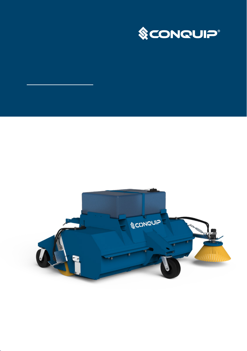
Specication
Item Product Code
Powerbrush SA800AN-02100
Height Width Length Weight Fork
Pockets
Tank
Capacity
1260mm 2700mm 2300mm 585kg 148x60mm 250 litres
Product Information
Parts Diagram
Powerbrush
Standard Unit
With Oponal Kerb Brush
Height Width Length Weight Fork
Pockets
Tank
Capacity
1260mm 2340mm 2180mm 560kg 148x60mm 250 litres
7
User Guide - Powerbrush
Product Information
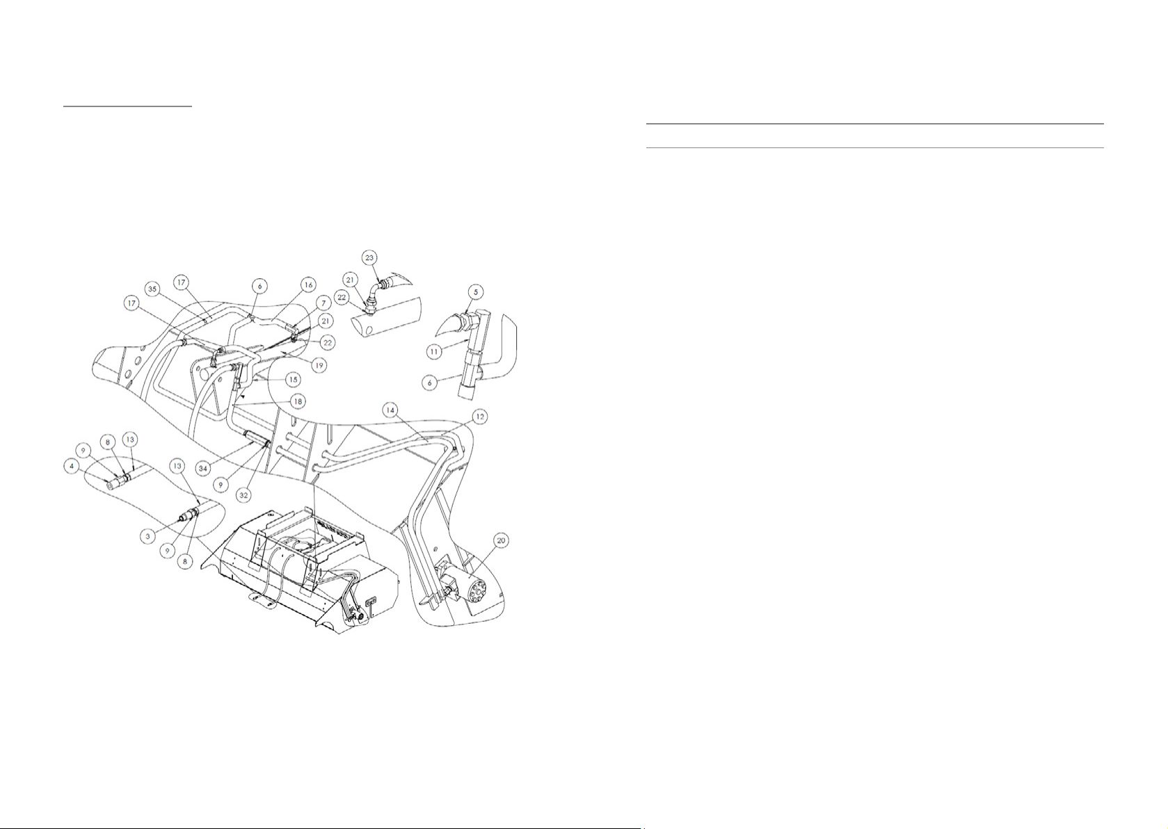
Parts Diagram
Powerbrush
Product Information
Parts Diagram
Powerbrush

9
User Guide - Powerbrush
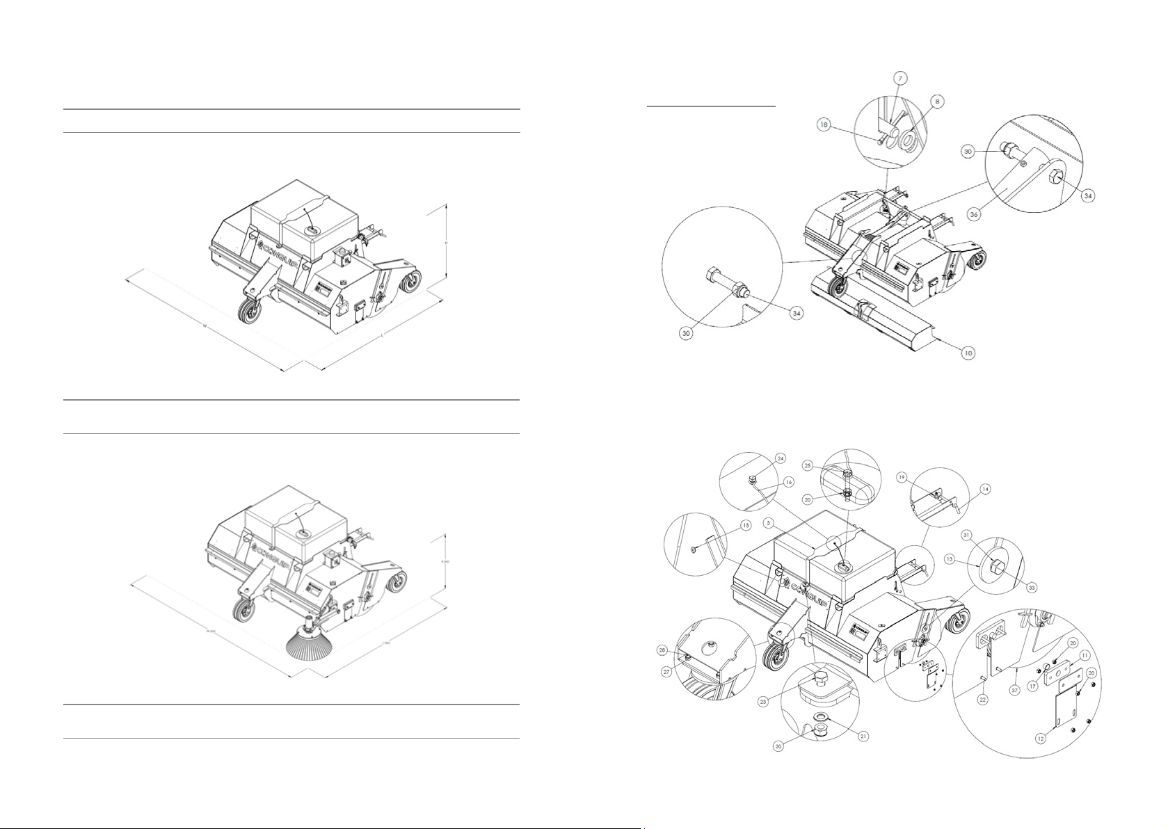
NOTE: These parts are for this model, they may differ for previous versions. Please contact Conquip with any queries.
Item Number Part Number Descripon Quanty
1 ZZ220169 Brush Adjustment Assembly 1
2 ZZ220170 Brush Adjustment Assembly c/w Bearing 1
3ZZ960079 Washer 4mm x OD: 15.5mm x ID:12.5mm 4
4 ZZ220173 Main Brush Sha, Length: 2065mm 1
5 ZZ220174 Water Tank Strap 1
6 ZZ220187 Sha Motor Insert Assembly 1
7ZZ220176 Fork Pocket Retaining Pins 2
8ZZ960078 Washer 6mm x OD:37mm x ID:21mm 2
9 ZZ220177 Sha Bearing Insert Assembly 1
10 ZZ960077 Washer 6mm x OD:73mm x ID:30.5mm 1
11 ZZ220178 Hopper Bearing Bracket 2
12 ZZ220179 Hopper Safety Guard 2
13 ZZ960063 Washer 6mm x OD: 70mm x ID: 17mm 2
14 ZZ990000 Heel Pin, 16mm dia. Max Pocket Width
180mm (Single) 2
15 NS800804 4.8 x 20mm Alu Large Flange Blind (Pop) Rivets 4
16 ZZ990510 Coated Galvanised Restraint Wire, 500mm c/w
Nylon Eye 1
17 ZZ960064 Sleeve Bearing, Oilon, OD: 25mm x ID:15mm
x 28mm 2
18 ZZ220167 Splined Hub, 8mm Key, 100mm L, OD: 50mm
Ø, ID: 25mm Ø 1
19 ZZ990009 Linch Pin 6mm x 42mm 4
20 NS800013 M10 Nyloc Nut 18
21 NS800262 M10 Steel Washer A BZP 2
22 NS800888 M10 x 30mm Coach Bolt 4
23 NS800666 M10 X 30 Hex Head set BZP 2
24 NS800066 M10 x 35 8.8 HT Hex Head Set Screw BZP 1
25 NS800622 M8 x 30 Hex Head Set Screw BZP 1
26 NS800860 M10x60 Coach Bolt 4
NOTE: These parts are for this model, they may differ for previous versions. Please contact Conquip with any queries.
Item Number Part Number Descripon Quanty
27 NS800015 M12 Nyloc Nut BZP 16
28 NS800889 M12 x 40 Hex Head Set Screws 8.8 HT 12
29 NS800817 M12 x 50 8.8 HT BZP Hex Set Screws 4
30 NS800121 M16 Nyloc Nuts BZP 2
31 NS800249 M16 Spring Washer 2
32 NS800566 M16 x 130 Bolts BZP 1
33 NS800379 M16 x 40 Set Screw 2
34 NS800801 M16 x 70 Bolt BZP 1
35 ZZ220003 Flanged Bearing, 30mm c/w Grease Nipple 1
36 ZZ960065 Hydraulic Cylinder, 20mm Ø Piston, 400mm
Stroke 1
37 ZZ270000 Brush 100% PPN 295mm x 600mm Ø 7
38 ZZ220185 Hydraulic Motor AGMR 160 1
39 ZZ990506 Water Tank, 250L, c/w Conquip Branding 1
40 ZZ270141 Swivel Castor, Heavy Duty, 305mm Wheel
Diameter 3
41 ZZ220180 Hydraulic Double Hose Clamp, 3/8” 2
42 ZZ220042 2m UPVC Pipe, ID: ½” 1
43 ZZ220040 90° Elbow, ½” Thread, ½” Solvent UPVC 1
44 ZZ220043 End Cap, ID: ½” Solvent UPVC 1
45 ZZ220181 Hydraulic Single Hose Clamp, ½” 2
46 ZZ220126 Water Tap 1
47 ZZ220125 PVC Water Hose 1
11
User Guide - Powerbrush
Product Information
Parts Diagram
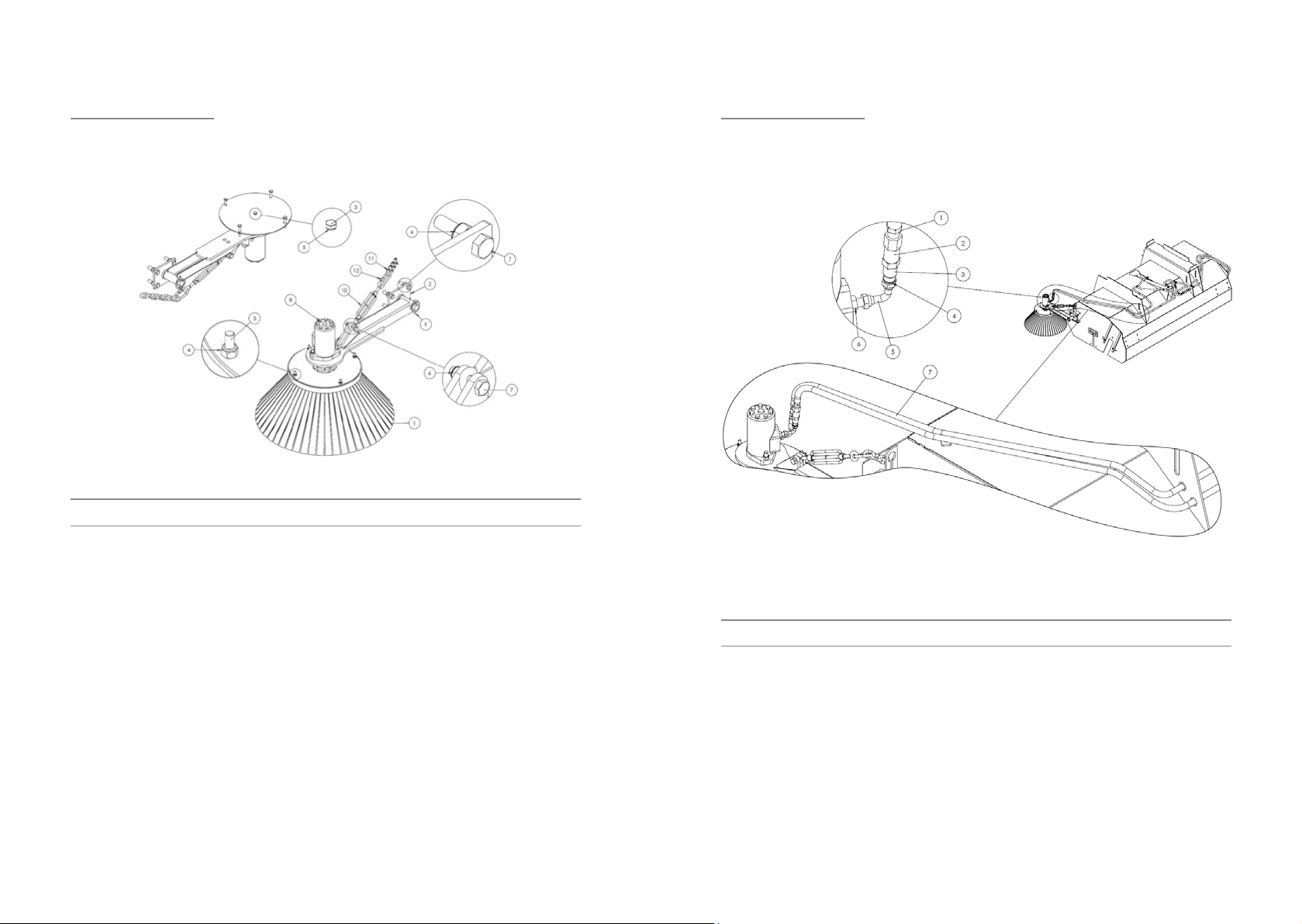
Powerbrush Kerb Brush Hydraulics
NOTE: These parts are for this model, they may differ for previous versions. Please contact Conquip with any queries.
NOTE: These parts are for this model, they may differ for previous versions. Please contact Conquip with any queries.
Item Number Part Number Descripon Quanty
1 ZZ220071 Male-Male Adaptor ⅜" X ⅜" BSP 3
2 ZZ220097 ½" Flat Face Female Quick Release Coupling 2
3ZZ220096 ½" Flat Face male Quick Release Coupling 2
4 ZZ990561 Rubber Bonded Seal ½" (Dowty Washer) 4
5 ZZ220202 Male -Female Adaptor Swept 90° 1/2" x 1/2"
BSP 2
6 ZZ220070 Male-Male Adaptor, 1/2" X 1/2" BSP 2
7ZZ220203 Hydraulic Hose, 3/8" Ø, 200mm, Ends: 3/8" F
/ 1/2" F 2
Item Number Part Number Descripon Quanty
1 ZZ220051 Poly Kerb Brush, 4 Fixing Bolts 1
2 ZZ220054 Kerb Brush Bracket 1
3NS800370 M8 x 50 HT Hex Bolt BZP 5
4 NS800011 M8 Nylon Inset Nut BZP 4
5 NS800378 M8 Spring Washer 1
6 NS800817 M12 x 50 8.8 HT BZP Hex Set Screws 7
7NS800015 M12 Nylon Inset Nut BZP 4
8ZZ220185 Hydraulic Motor AGMR 160 1
9 ZZ990009 Linch Pin 6mm x 42mm 1
10 ZZ220054 Kerb Brush Bracket 1
11 ZZ990515 Chain, Galvanised, 8mm x 52mm x 32mm Long
Link (per metre) 4
12 ZZ110009 Quick Link, 8mm 1
Product Information
Parts Diagram
Powerbrush Kerb Brush
13
User Guide - Powerbrush
Product Information
Parts Diagram
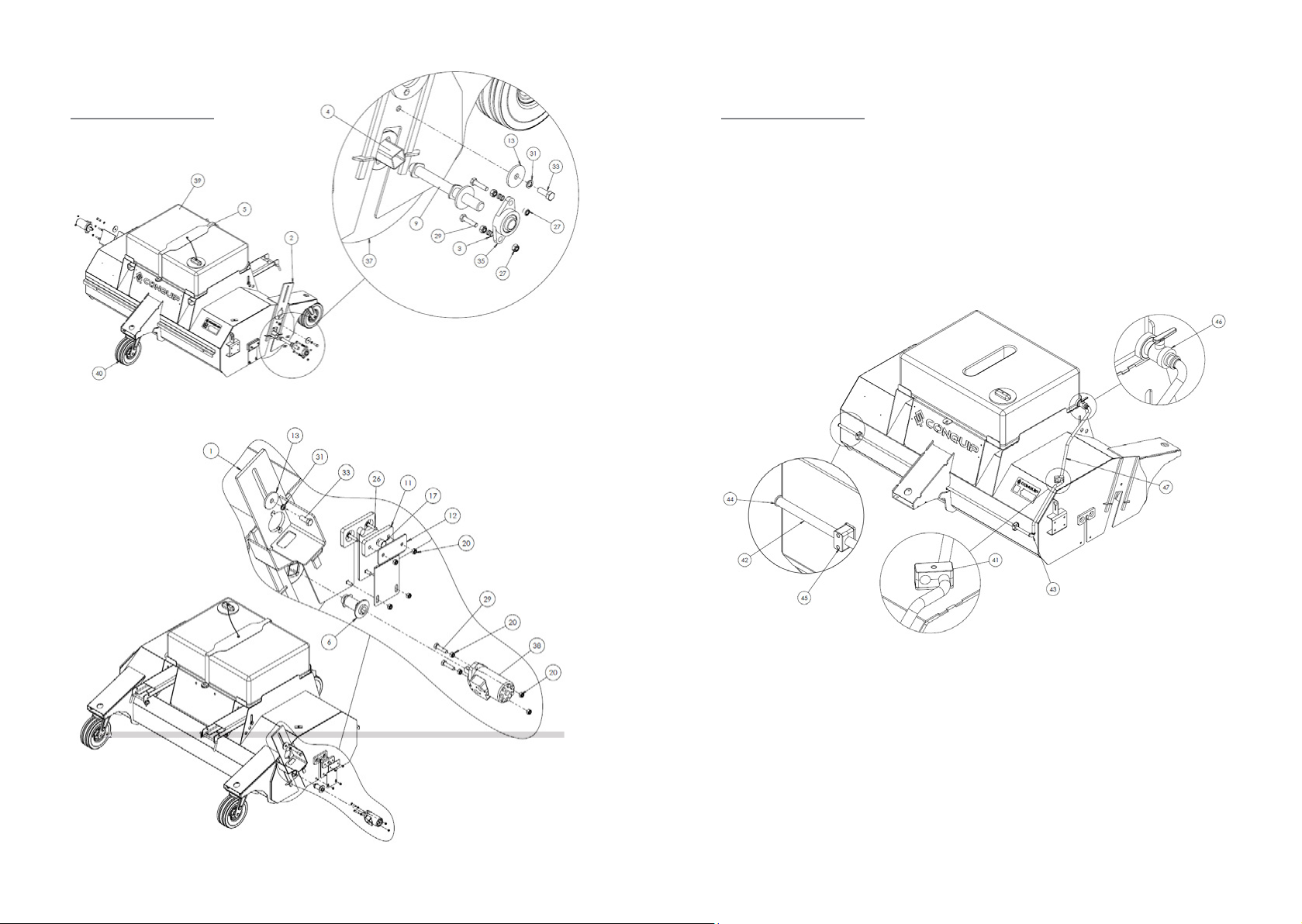
Powerbrush without Kerb Brush Hydraulics
NOTE: These parts are for this model, they may differ for previous versions. Please contact Conquip with any queries.
Item Number Part Number Descripon Quanty
1 ZZ220071 Male-Male Adaptor ⅜" X ⅜" BSP 5
2 ZZ990562 Rubber Bonded Seal ⅜" (Dowty Washer) 4
3ZZ220092 ⅜" Flat Face male Quick Release Coupling 1
4 ZZ220093 ⅜" Flat Face Female Quick Release Coupling 1
5 ZZ220193 Bulkhead Fing c/w Locknut, ⅜" BSP 2
6 ZZ220123 ⅜" M/M/M Tee Piece 2
7ZZ220122 Male -Female Adaptor Compact 90° 3/8" x
3/8" BSP 3
8ZZ220137 Male-Male Adaptor, 3/8" X 1/2" BSP 6
9 ZZ990561 Rubber Bonded Seal ½" (Dowty Washer) 6
10 ZZ220138 1 way Valve Female to Female 1/2in 1
11 ZZ220194 Female -Female Adaptor Compact 90° 3/8" x
3/8" BSP 1
12 ZZ220195 Hydraulic Hose, 3/8" Ø, 2200mm, Ends: 3/8"
F / 3/8" F 1
13 ZZ220184 Hydraulic Hose, 3/8" Ø, 2100mm, Ends: 3/8"
F / 3/8" F 2
14 ZZ220196 Hydraulic Hose, 3/8" Ø, 1600mm, Ends: 3/8"
F / 3/8" F 1
15 ZZ220197 Hydraulic Hose, 3/8" Ø, 470mm, Ends: 3/8" F
/ 3/8" F 1
16 ZZ220198 Hydraulic Hose, 3/8" Ø, 2100mm,Ends: 3/8" F /
3/8" Compact 90° F 1
17 ZZ220199 Hydraulic Hose, 3/8" Ø, 220mm, Ends: 3/8" F
/ 3/8" F 2
18 ZZ220200 Hydraulic Hose, 3/8" Ø, 170mm, Ends: 3/8" F
/ 3/8" F 1
19 ZZ960065 Hydraulic Cylinder, 20mm Ø Piston, 400mm
Stroke 1
20 ZZ220185 Hydraulic Motor AGMR 160 1
21 ZZ220201 Male-Male Adaptor, 1/4" X 3/8" BSP 2
22 ZZ990563 Rubber Bonded Seal ¼" (Dowty Washer) 2
15
User Guide - Powerbrush
Original Working Instructions
Usage Instructions
Important Usage Notes
• The Powerbrush is supplied with heel pins that must be ed correctly
before use. If the heel pins are missing do not use the equipment or t
alternaves - contact Conquip Engineering Group for a replacement.
• Drain the water tank in cold weather to prevent freezing.
• Keep the hydraulic hoses safely o the ground to avoid them geng
damaged.
• DO NOT disconnect the hydraulic hoses unless the pressure from the auxiliary
service has been released.
• Never allow brick banding, barbed wire, or any straps to be picked up by the
Powerbrush.
• Always ensure the hydraulic system is in operaon before use.
• DO NOT drive directly over xed objects, such as manholes.
• Close the hopper fully when not using the Powerbrush to avoid pressure.
Assembly Instrucons for the Oponal Kerb Brush
1. Bolt on the Kerb Brush Pin Bracket (ZZ220054) to the Powerbrush, using 4
M12 x 50mm bolts, provided.
2. Slide the gulley brush arm onto the pin.
3. Insert the linch pin to secure the arm to the bracket.
4. Pass the chain through the anchor point to a posion where the bristle of the
kerb brush is just o the oor.
5. Use the turn buckle for ne adjustment to a point where the front bristles are
just touching the oor with a small amount of deecon.
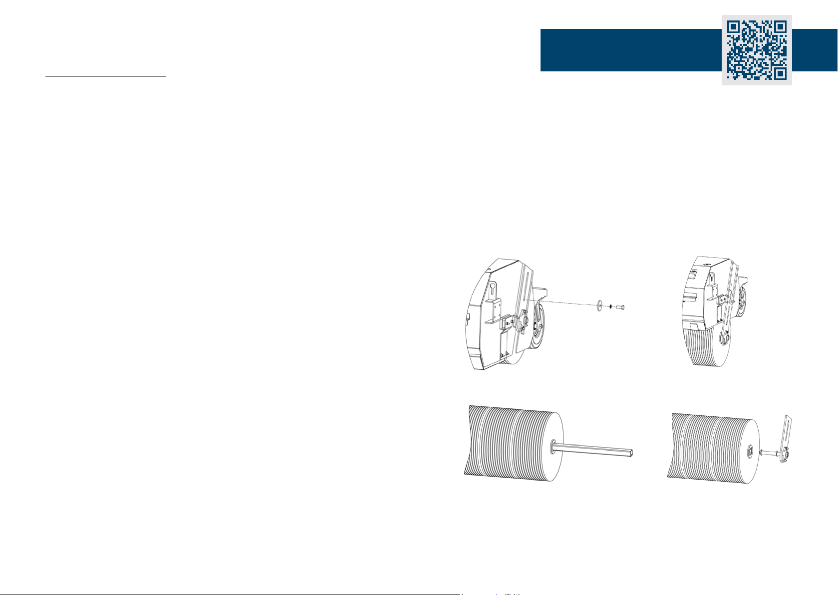
Assembly Instrucons for Replacing the Main Brush Secons
1. Remove the bolt and washer from the top plate xing on both sides of the
Powerbrush body, and detach the hydraulic hoses.
2. With the xings now removed on both sides, li the Powerbrush with the
forkli. The brush, along with any xings aached, will now slide down the
plate guide and detach itself from the Powerbrush body.
3. Once the brush is fully detached from the Powerbrush body, detach the
xing, bearing and bearing sha (as shown).
4. Once xing and bearing parts are removed, the brush secons with the brush
can pull out.
Scan for video guide!
17
User Guide - Powerbrush
Pre-Use Checklist
1. Before using the Powerbrush, charge the baery by inserng the 110v plug
into the socket. Once fully charged, remove the plug from the socket.
2. Ensure the water tap is in the ‘o posion’ before aempng to ll the water
tank.
3. Remove the water tank cap, ll the tank with water and replace the cap.
4. Check that the wheels of the Powerbrush are free to swivel, not damaged
and the bearings are well greased.
5. Check the hydraulic hoses and connecons for leaks and ensure they are not
damaged.
6. Check there are 2 fork retaining pins in the heel pin storage slots that can be
secured aer the telehandler has inserted the forks into the fork pockets.
7. If you have a kerb brush ed, check the adjustment chain is in its bracket
and the linch pin is secure.
Seng up the Powerbrush
1. To connect the Powerbrush to your forkli, set the machine’s forks to the
correct width for the Powerbrush fork pockets. Make sure that they are
equidistant from the centre.
2. Drive the forkli/ telehandler to the Powerbrush. Align the forks with the
Powerbrush fork pockets and fully insert the forks.
3. Fit the fork retaining pins behind the heel of the forks to secure the
Powerbrush to the machine.
4. Apply the park brake and switch o the forkli engine.
5. Release any pressure in the auxiliary hydraulic line of the machine by
operang the control lever.
6. Detach the main hose couplings on the Powerbrush and connect them to
the 2 outputs on the machine. The quick release female on the Powerbrush
connects to the male on the machine and the male to the female.
7. Check that the main brush is rotang and the hopper is opening and closing
fully.
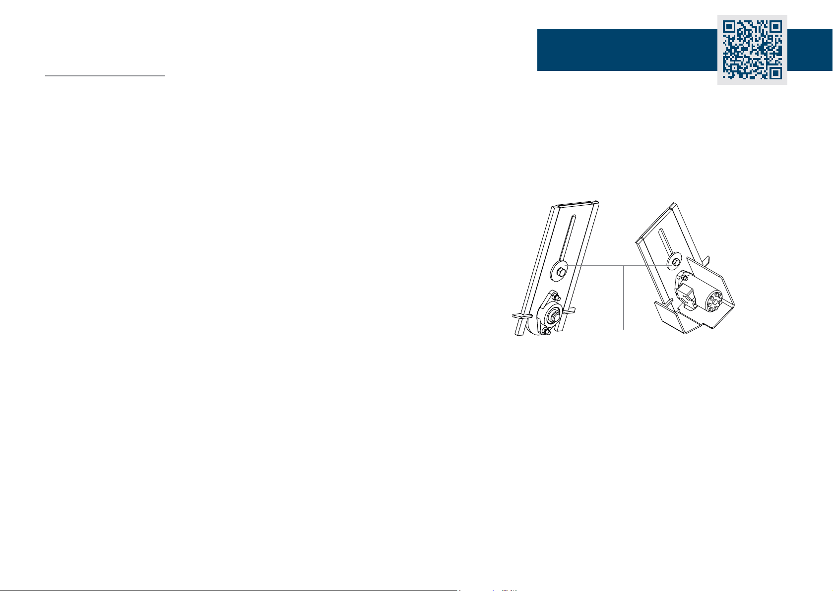
8. Ensure that the main brush is adjusted correctly. Always set up the
Powerbrush on a level surface. The bristles should be touching the ground
very slightly with a small deecon where they meet the oor.
9. To adjust the brush, undo bolt ‘A’ on one side of the brush (see diagram
below) and apply a small amount of pressure to push the brush to the
ground. Re-ghten the bolt. Repeat this procedure to the other side of the
brush.
A
Scan for video guide!
10. The Powerbrush is now ready for use.
NOTE: Conguraon may dier on dierent forkli makes and models.
Original Working Instructions
Usage Instructions

19
User Guide - Powerbrush
Original Working Instructions
Usage Instructions
Using the Powerbrush
1. Open the water tap, to allow water to dribble evenly from the dispenser bar
at the front of the Powerbrush.
2. For the pressurised water spray model, turn the electric swch on.
3. Lower the brush to the oor.
4. Ensure that the oang forks are centralised and the forks are level.
5. Acvate the brush by operang the hydraulic circuit of the forkli or
telehandler.
6. Drive forward at a suitable speed to achieve the desired sweep results.
7. Once the hopper is full, li the Powerbrush to a suitable locaon and reverse
the ow of the hydraulic circuit to empty the hopper.
Removing the Powerbrush from your Machine
1. To remove the Powerbrush from a forkli or telehandler, rst park in a
suitable place away from site trac but somewhere that is easily accessible
when the unit is required again.
2. Apply the park brake and switch of the forkli engine.
3. Operate the auxiliary control lever, without the engine running, to release the
pressure and close the hopper.
Closing the hopper will prevent a build up in the hydraulic hoses.
4. Exit the machine cab to follow the next steps.
5. Turn the water tap to the ‘o posion’. If using the pressurised water spray,
make sure the power supply switch is turned o so that the orange beacon is
no longer ashing.
In freezing condions, remove the water hose and drain the tank.
6. Remove the hydraulic hoses from the 2 outputs on the arm of the machine.
CAUTION: Use gloves as the connecons will be hot due to hydraulic oil
passing through the hoses.
7. Remove the fork retaining pins and ret them into their storage holes.
8. Return to the machine’s cab to detach the Powerbrush from the forkli or
telehandler.
9. Slowly reverse the forkli or telehandler to remove the forks from the fork
pockets.
10. Conquip advise lubricang the grease points aer use, as demonstrated in
our ‘How to use the Powerbrush’ video. Scan the QR code at the top of this
User Guide to watch.
11. Recharge the baery.
Scan for video guide!
Altri manuali per Powerbrush
2
Questo manuale è adatto per i seguenti modelli
1
Indice
Altri manuali Conquip Soffiatore


