Contacta STS-K072 Manuale operativo

Installation &
User Guide
December 2020
Window Intercom System
Speaker Pod and Screen Mounted
Microphone - STS-K072

2
Contents
Product Overview
Components
Connections
Installation Instructions
Speaker & Microphone Kit Installation
StaSideInstallation
Customer/Visitor Installation
Hearing Loop Installation
AmplierSetup
Troubleshooting
Engineer’s Mode
3
3
4
5
6
6
7
9
10
12
13
Contactahasapolicyofcontinuousproductdevelopment,andthereforesmallspecication
changesmaynotbereectedinthismanual.Images,labels,packaging,accessoriesandproduct
coloursaresubjecttochangewithoutnotice.
3
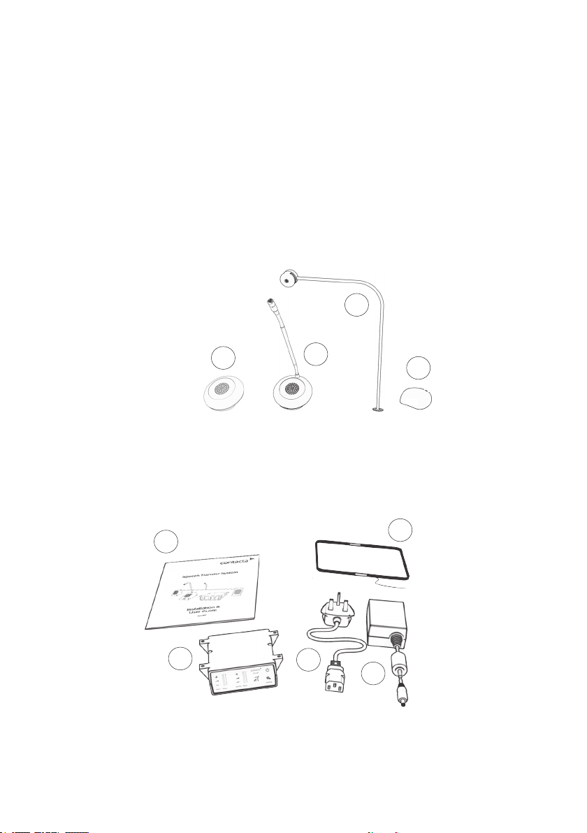
Speaker & Microphone Components
Product Overview
Window intercom systems provide assistance for clear communication where
normal speech is impaired by use of glass, a security screen or other similar
barriers.
There is an optional hearing loop facility, providing additional assistance for
hearingdevicewearers.
1. Installation and User Manual
2. Amplier
3. IEC Lead
4. Power Supply
5. HearingLoopAerial
(optional)
Fixing Kit:
• Adhesive Clip x 10
• No.6x1/2”CountersunkScrewsx15
• P-Clips x 6
5
General Components
1. Speaker Pod
2. StaPod
3. Screen Mounted Microphone
with Bent Stem
4
3
2
1
1
3
24
4
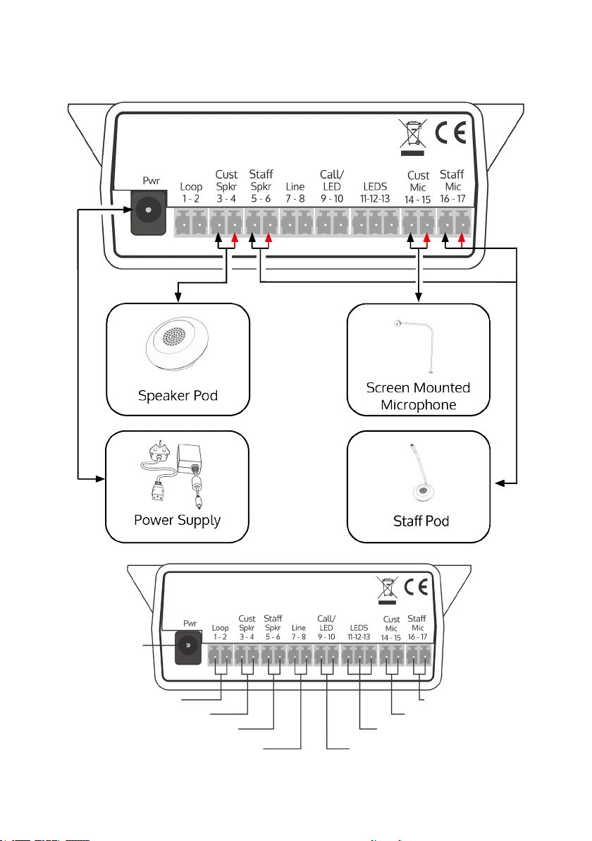
Connections
LED connection or alert tone (if required)
CondenceLEDtoconrmthesystemispowered
oranalerttonefortheattentionofsta
Stamicrophone
Customer/visitor microphone
CondenceLED(ifrequired)forstatusalerts
and fault detection
Hearing loop aerial
Line in connection for
external audio source
Staspeaker
Customer/visitor speaker
Power input
connection
Use power supply
through ground
supply only
5
Werecommendthatinstallationiscarriedoutbyaqualiedengineer,
adheringtorelevantstandards.
Checkthecontentsoftheboxtofamiliariseyourselfwiththecomponents.
Installation Instructions
A basic toolkit recommended to install the system will include:
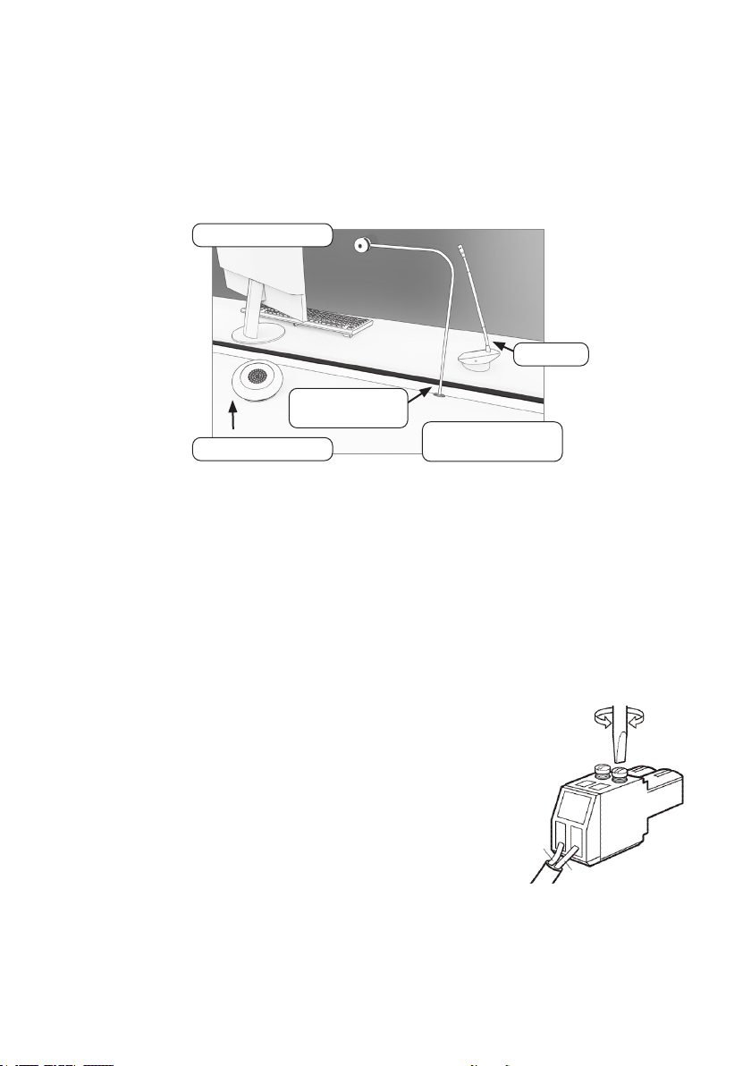
Trim cables if necessary (excluding the power supply)
to the required length to connect to the back of the
amplier.Bareapproximately6mmofthecableendsto
connecttothe2pinplugs.
• Wire Cutters/Strippers
• Tape Measure
• Pencil or Marker Pen
• Cable Ties
• Trunking
• Screwdrivers(FlatorBlade2.5mm
and Phillips Head PH2)
• Battery or Mains Drill
• Drillbits: 2mm, 3mm, 5mm and 7mm
• Cable Tacking Gun (10mm)
Recommended Tools
Staff Counter Side
Customer / Visitor
Counter Side
StaPod
Screen Mounted
Microphone
Speaker Pod
Negative -
or screened cable
Positive +

6
1. Placetheamplierunderthestacounter,ensuringthatitwillnot
obstructstawhentheyaresitting.
2. Markthefourxingpointsfortheamplierunderthecounter.
4. Drillandxtheamplierinplaceusingthesuppliedscrews.
6. Installtheamplier’spowersupplyclosetoapowersocketoutletusing
thesuppliedmountingbracketandxingscrews.
Fixing points
AmplierInstallation
7
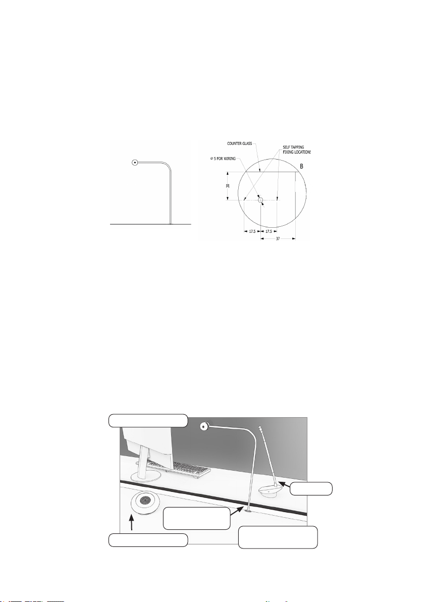
Microphone & Speaker Installation
1. Position the screen mounted microphone stem’s on the customer side of
thecountertop.
2. Markthe2xingpointsand1cableroutereadyfordrilling(seethe
diagrambelow).
3. Drillpilotholesforthexingsandacableholeifneccesary.
4. Feedwiringthroughthecableholebacktotheamplierandxthe
microphoneinplaceusingthesuppliedscrews.
5. Fix the microphone head to the screen using the double-sided pad
supplied.
6. Placethestapodonthestasideofthecountertop,ensuringit
doesnotcauseanobstructionandisasclosetostaaspossible.The
recommended minimum distance between this pod and the screen
mountedmicrophoneis300mm.
Staff Counter Side
Customer / Visitor
Counter Side
StaPod
Screen Mounted
Microphone
Speaker Pod

8
7. Place the speaker pod on the customer side of the counter top, ensuring it
doesnotcauseanobstruction.
8. Speakerpodsandstapodscanbeeitherfreestandingorxed.Moveto
step14ifyoudonotwishtoxthepodstothecounter.
9. Usecablemanagementholesinthecountertorunthestapodand
speakerpodcablestotheamplier.Iftherearenotalreadycable
managementholes,drillsuitablelocationsneartherearofboththesta
andcustomersidesofthecounter.
10. Removethetopofthepodstogainaccesstothexingpoints.
11. Markthetwoxingpointsonthebottomofbothpods.Thenmarktwo
cable holes to be drilled, one for both the customer/visitor side and the
staside.
12. Ensuretherewillbeaccesstoretrievethecablesthendrilltheholes.
13. Fixthepodstotheirrespectivecounters.
14. Feedthepods’wiresthroughthecablemanagementholes.
15. Routeallcablingneatlytotheamplierlocationonthestaside.

9
Theaerialshouldbexedunderthedesk-toporcountercentrallyonthe
customer or visitor side, one half mounted horizontally under the counter and
theotherhalfmountedvertically,facingthecustomer/visitor(asintherst
scenariobelow).
Position the aerial under the counter using either the provided P-clips
oranotherxingmethodofyourchoice.Seethediagrambelowfor
recommendedpositioning.
Aistheoptimumlayoutforacounterhearingloop.
B and C are acceptable only if A is not possible and the layout is aligned so
thatthemagneticeldwillbedirectedtowardsuser’sheadheights.
Ensureallhearingloopsignageisdisplayedclearly.
X
X
Hearing Loop Installation
(Optional)
A B C
10
AmplierSetup
1. Connectallgreenplugstothebackoftheamplier,followingthe
locationsprintedabovethesockets(seepage4).
2. PowerontheamplierbypressingtheOn/Obutton.
3. Whenpoweredandinnormaloperationalmodetheamplierwilldisplay
VolumeInLED1andVolumeOutLED1assteadygreen.
4. Whentheamplierisswitchedo,allaudioismutedandnoneofthe
LEDsareilluminated.Pressinganybuttonwillturntheamplieronagain.
5. AdjustVolumeInandVolumeOuttoacomfortablelevel.
6. Press and hold the Volume In (+) or (-) buttons to increase or decrease the
level.ThecorrespondingLEDbarwillshowthevolumesetting.
6. Ensure the mouse microphones are placed as close to their intended
usersaspossible.
7. Checktheamplierisfullyfunctionalbyensuringthered‘fault’lightis
NOTshowingonthefront.
8. The Amplifier is now set up.
OurWindowIntercomSystemampliersarepre-settovolumelevels
suitablefornearlyallusers.ShouldyouneedtoadjusttheMaximum
Volume,DuckingorHearingLooplevelsoutsideofthepre-setamplier
parameters,useEngineer’sMode(seepage13).
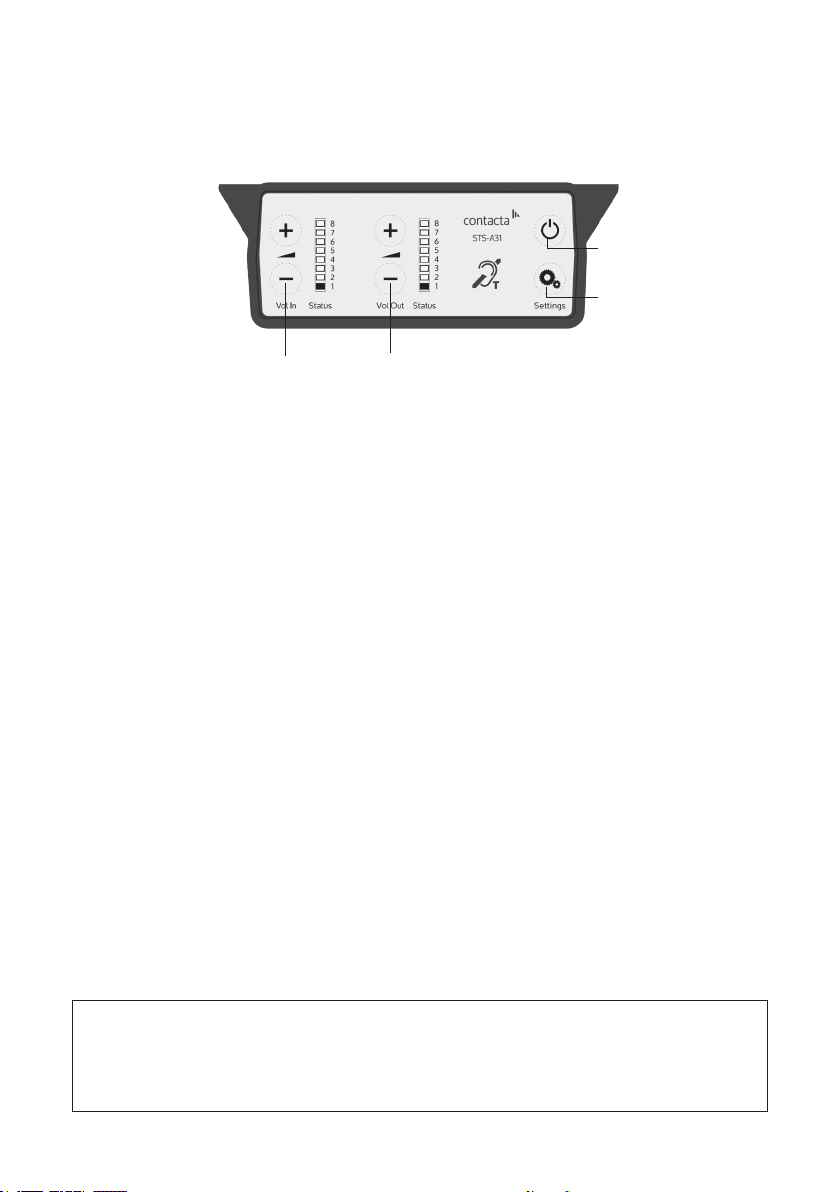
Overview of Front Panel Buttons
Volume In (Customer/Visitor to Staff)
Increase and decrease
Volume Out (Staff to Customer/Visitor)
Increase and decrease
Settings
On/O
Setup
Indice
Altri manuali Contacta Microfono


