Contec CS2000 Manuale utente

INTELLIGENT LABEL SENSORS
OPERATIONS MANUAL
CS2000 & CS2000-QDCS2000 & CS2000-QDCS2000 & CS2000-QD
Control Technologies
www.con-tech.com

Table of Contents
General Information
Features
Diagram
CS2000 Quick Start
CS2000-QD Quick Start
Installation
Mounting
CS2000 Wiring
CS2000-QD Wiring
Operation
Label Placement
Push-Button Functions
LED Functions
Operation Features
Output Mode
Light/Dark Operation
Contrast Setting
Factory Settings
Adjusting Label Sensitivity
Overview
Easy Setup
Possible Problems
Missing Label Compensation
Overview
Enabling Missing Label Compensation
Disabling Missing Label Compensation
Program Mode
Entering Program Mode
Table of Features
Changing a Feature
Exiting Program Mode
Specifications
General
Dimensions
Cleaning Instructions
Warranty Terms & Conditions
1
1
2
3
4
5
5
6
7
8
8
8
9
9
9
9
9
9
10
10
10
10
11
11
11
11
12
12
12
12
12
13
13
14
15
16
...............................................................................................
.......................................................................................................
........................................................................................................
........................................................................................
...................................................................................
............................................................................................................
.......................................................................................................
..............................................................................................
.........................................................................................
..............................................................................................................
.............................................................................................
.....................................................................................
................................................................................................
.........................................................................................
.........................................................................................
.............................................................................
....................................................................................
.............................................................................................
.....................................................................................
.......................................................................................................
....................................................................................................
..........................................................................................
..................................................................................
.......................................................................................................
...............................................................
..............................................................
......................................................................................................
..................................................................................
...........................................................................................
........................................................................................
....................................................................................
.......................................................................................................
........................................................................................................
...................................................................................................
............................................................................................
...............................................................................

- 1 -
General Information
Features:
• 10 to 30 VDC input - reverse polarity protected
• Fast RISC microprocessor controlled
• Easy one touch setup - label sensitivity easily adjusted, to the optimal setting, by
the push of a button
• Missing label compensation - outputs a stop pulse even when a label is missing
• Level shift or leading edge pulse output selectable
• Light or dark operation selectable
• Low label contrast setting available
• Push-button may be momentarily depressed to output a stop pulse - very useful
during machine setup
• All settings saved in nonvolatile memory (EEPROM) - settings are not affected
by power loss
• NPN or PNP output selectable - 100mA, open collector, reverse polarity and
short circuit protected
• Precision machined and double anodized aluminum housing
• 8 mounting holes - allows for many different mounting options
• Large throat - 3" deep x 0.093 wide
• Optional 6" quick disconnect M12 - 4 pin male cable/connector (Turck P/N RS4.4T-2)

- 2 -
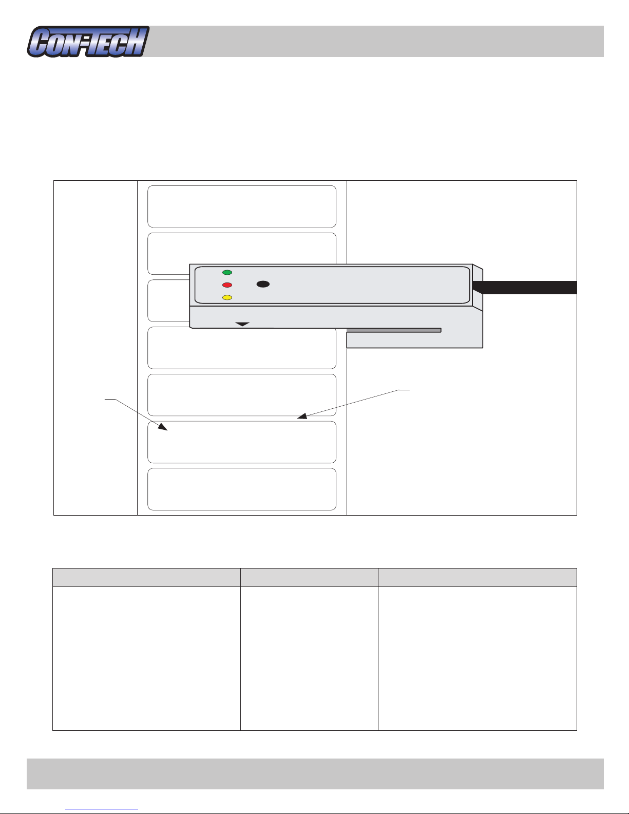
General Information
Yellow LED:
Indicates label
backing (web)
Push-button
Red LED:
Indicates output state
Green LED:
Indicates label
+ label backing
Optional 6" Quick Disconnect
4 Pin Male Cable/Connector
#8-32 Mounting Holes
EASY SETUP
WEB OUT LABEL
1.
2.
3.
4.
Position web
under sensing
area and hold
button down until
yellow LED
comes on.
Release button
and yellow LED
will flash.
Move label under
sensing area and
green LED will
come on.
Setup complete.
CS2000
Throat
Sensing
Area
#8-32 Mounting Holes (x6)
CS2000 Diagram:

- 3 -
General Information
CS2000 Quick Start:
1. Connect red wire to supply voltage
2. Connect black wire to supply common
3. For NPN Output - connect orange wire to black wire
For PNP Output - connect orange wire to red wire
4. Connect white wire to your controller - refer to page 6 for wiring diagrams
5. Turn on power
6. Peel off a label and position the label backing (web) under the sensing area
7. Depress the push-button until the yellow LED comes on (1 sec.), then release
8. The yellow LED will begin flashing
9. Move a label under the sensing area and the green LED will come on
10. The label sensitivity is now adjusted and the sensor should function correctly
11. The yellow LED indicates when label backing (web) is detected
12. The green LED indicates when label over label backing is detected
13. The red LED indicates when the output is active - NPN sinking or PNP sourcing

- 4 -
General Information
CS2000-QD Quick Start:
1. Plug the CS2000-QD's male connector into a suitable 4 pin female connector
2. Connect brown wire to supply voltage
3. Connect blue wire to supply common
4. For NPN Output - connect black wire to blue wire
For PNP Output - connect black wire to brown wire
5. Connect white wire to your controller - refer to page 7 for wiring diagrams
6. Turn on power
7. Peel off a label and position the label backing (web) under the sensing area
8. Depress the push-button until the yellow LED comes on (1 sec.), then release
9. The yellow LED will begin flashing
10. Move a label under the sensing area and the green LED will come on
11. The label sensitivity is now adjusted and the sensor should function correctly
12. The yellow LED indicates when label backing (web) is detected
13. The green LED indicates when label over label backing is detected
14. The red LED indicates when the output is active - NPN sinking or PNP sourcing

- 5 -
Installation
Mounting:
The CS2000 comes with 8 mounting holes allowing for many different mounting options. The
holes are tapped for #8-32 screws and are 0.31" deep. We suggest using #8-32 x 3/8"
stainless steel screws. Some different options are shown below.
* To avoid electro-static discharge and sensor malfunction, the CS2000 should be mounted to
a grounded metal surface. If this is not possible, a grounding wire should be connected from
one of the mounting screws to a suitable ground.
FORK

- 6 -
Installation
CS2000 Wiring:
The CS2000 comes with an 8' - 4 conductor cable. Refer below for wire designations.
RED = 10-30 VDC
BLK = Common
WHT = Output
ORN = NPN / PNP Output Selector
Optoisolator
CS2000
RED
10-30V
LOAD
BLK
WHT
ORN WHT
ORN
WHT
ORN
WHT
ORN
WHT
+5V
5V Logic
1K
1/4W
Supply
Voltage
12V = 1K 1/4W
24V = 2K 1/4W
12V = 1K 1/4W
24V = 2K 1/4W
Optoisolator
*5V Com. and 10-30V Com.
must be connected together
*Output Source Com. and Supply
Com. must be connected together
*Resistor values are to source approx.
10mA to the optoisolator
*Resistor values are to source approx.
10mA to the optoisolator
ORN
WHT
ORN
CS2000
CS2000
CS2000
CS2000
CS2000
Interfacing to Load - NPN Output:
Interfacing to 5V Logic - NPN Output: Sourcing Other than Supply Voltage - PNP Output:
Interfacing to Optoisolator - PNP Output:Interfacing to Optoisolator - NPN Output:
Interfacing to Load - PNP Output:
LOAD
LOAD
RED
10-30V
RED
RED
10-30V
BLK
BLK 10-30V
BLK
RED
10-30V
BLK
RED
BLK 10-30V
Output
Source
Voltage
10-30V

- 7 -
Installation
CS2000-QD Wiring:
The CS2000-QD comes with a 6" quick disconnect M12 - 4 pin male cable/connector (Turck
P/N RS4.4T-2). Refer below for wire designations.
Pin 1. BRN = 10-30 VDC
Pin 2. WHT = Output
Pin 3. BLU = Common
Pin 4. BLK = NPN / PNP Output Selector
Optoisolator
CS2000-QD
BRN
10-30V
LOAD
BLU
WHT
BLK WHT
BLK
WHT
BLK
WHT
BLK
WHT
+5V
5V Logic
1K
1/4W
Supply
Voltage
12V = 1K 1/4W
24V = 2K 1/4W
12V = 1K 1/4W
24V = 2K 1/4W
Optoisolator
*5V Com. and 10-30V Com.
must be connected together
*Output Source Com. and Supply
Com. must be connected together
*Resistor values are to source approx.
10mA to the optoisolator
*Resistor values are to source approx.
10mA to the optoisolator
BLK
WHT
BLK
CS2000-QD
CS2000-QD
CS2000-QD
CS2000-QD
CS2000-QD
Interfacing to Load - NPN Output:
Interfacing to 5V Logic - NPN Output: Sourcing Other than Supply Voltage - PNP Output:
Interfacing to Optoisolator - PNP Output:Interfacing to Optoisolator - NPN Output:
Interfacing to Load - PNP Output:
LOAD
LOAD
BRN
10-30V
BRN
BRN
10-30V
BLU
BLU 10-30V
BLU
BRN
10-30V
BLU
BRN
BLU 10-30V
Output
Source
Voltage
10-30V
4
1
2
3
ACME LABELS
ACME LABELS
AC
ACME LABELS
ACME LABELS
ACME LABELS
ACME LABELS
- 8 -
Operation
Label Placement:
For best results, position straight edge of label under the sensing area. Try to avoid sensing
on rounded corners or other curved areas. Refer to diagram below.
Less than 1 second
1 to less than 5 seconds
5 to less than 10 seconds
30+ seconds
YEL/GRN - off
YEL - on
GRN - on
YEL/GRN - toggle
Outputs a stop pulse
Adjust Label Sensitivity
(refer to page 10)
Set Missing Label Compensation
(refer to page 11)
Enter Program Mode
(refer to page 12)
Push-button is depressed for... LED's Function
Push-button Functions:
Label Web (label backing)
Sensing
Area
Questo manuale è adatto per i seguenti modelli
2
Indice


