Contractor DBS-100RCS Manuale utente
CONTRACOR GmbH
42329 Wuppertal
Germany
Art. 10405/10410
DBS-100RCS
DBS-200RCS
Abrasive Blasting Machines
USER MANUAL
Version 2.0
Sandstrahlmaschinen
BEDIENUNGSANLEITUNG
Version 2.0
Seite 26.
Аппараты
абразивоструйные
РУКОВОДСТВО
ПОЛЬЗОВАТЕЛЯ
Версия 2.0
стр. 50.
РУССКИЙ
DEUTSCHENGLISH

2
ENGLISH
CONTRACOR® Version 2.0
Contents
1. Safety 3
2. Package and description 4
3. Set-up, operation and shut-down 6
4. Abrasive blasting operations 8
5. Maintenance 10
6. Troubleshooting 12
7. General drawings 14
8. Instructions for Use Pressure Vessel of
Abrasive Blasting Machine CONTRACOR DBS 19
9. Warranty and warranty service regulations 24
ATTENTION!
READ AND FULLY UNDERSTAND THIS MANUAL BEFORE STARTING WORK.
THE FOLLOWING INFORMATION IS IMPORTANT FOR SAFETY AND HEALTH OF
OPERATOR AND PERSONNEL IN VICINITY.
ATTENTION!
BUYING THE MACHINE, PLEASE, REQUEST TO FILL IN THE GUARANTEE CARD
CORRECTLY!
FAILURE TO PRODUCE A FILLED-IN FORM WILL MAKE YOUR GUARANTEE
INVALID.
3
ENGLISH
CONTRACOR® DBS-RCS Art. 10405/10410
1. Safety.
ATTENTION!
SAFETY MEASURES FOR ABRASIVE BLASTING.
1. You must wear protective equipment: a helmet with positive
air feed, breathing air lter, protection suit, leather gloves, and
special footwear.
2. Do not use worn or damaged equipment during operation.
3. Point the nozzle only at the area to be cleaned.
4. Use only dry well-sieved abrasive materials, appropriate for
abrasive blasting operations.
5. All personnel without protection equipment should be outside the
zone of blasting operations.
6. Before starting abrasive blasting operations you must:
— Ensure that hoses and ttings are not worn;
— Fix hose couplings with wire;
— Ensure that air is fed to the helmet;
— Ensure that pressurizing valve is in correct position;
— Ensure that the machine is in steady state position
4
ENGLISH
CONTRACOR® Version 2.0
2. Package and description.

5
ENGLISH
CONTRACOR® DBS-RCS Art. 10405/10410
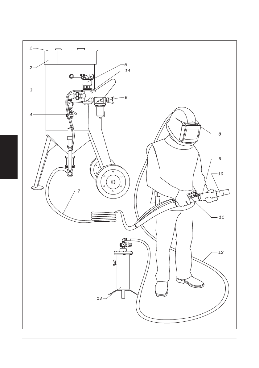
Fig. 2.1.
1 — cover,
2 — screen,
3 — machine tank,
4 — RC hose TWINLINE,
5 — Remote control valve RCV,
6 — moisture and oil separator
CAF-1,
7 — abrasive blasting hose
UNIFLEX,
8 — operator helmet COMFORT,
9 — nozzle holder,
10 — nozzle,
11 — RC handle DMH,
12 — breathing air hose,
13 — breath air lter BAF-1,
14 — safety ball valve.
2.1. Package.
Table. 2.1.
Order code Model Description, package
10405 DBS-100RCS Abrasive Blasting Machine, 100 L,
screen,
cover,
moisture and oil separator lter CAF-1,
remote control valve RCV,
remote control handle DMH,
steel abrasives valve SGV,
twin hose in RC TWINLINE 40m,
tting set for RC hose.
10410 DBS-200RCS Abrasive Blasting Machine, 200l,
screen, cover,
moisture and oil separator lter CAF-1,
remote control valve RCV,
remote control handle DMH,
steel abrasives valve SGV,
RC twin hose TWINLINE 40m,
tting set for RC hose.
10970 RCV Remote control valve (5, Fig.2.1)
10940 DMH Remote control handle (11, Fig.2.1)
12103 TWINLINE Remote control twin hose, d=6mm, roll 40 m
(4, Fig.2.1)
6
ENGLISH
CONTRACOR® Version 2.0
3. Set-up, operation and shut-down.
3.1. Preparation for operation.
For remote control system start up you should follow these instructions:
1. If necessary shorten the RC hose to the length of the used blasting hose.
2. Connect the ttings provided in the package with RC hose. Connect RC hose to
distant control handle DMH from one side and TWINLINE line of the blasting machine
from another side.
ATTENTION!
DO NOT TIGHTEN UNIONS TOO MUCH, IN PARTICULAR THE UNIONS OF RC
HANDLE. IT CAN DAMAGE SOME COMPONENTS AND CAUSE AN AIR LEAK.
3. Ensure that all connections are leak-proof.
4. Ensure that all connections on the RC valve and RC handle DMH are connected
properly, and according to the color. Transverse joint will make the system non-
operational.
5. Fix RC handle DMH to the blasting hose, using clamp bands right behind the nozzle
holder.
6. We recommend to connect a twin hose Twinline to the blasting hose using clamp
bands every 1.5 m.

7
ENGLISH
CONTRACOR® DBS-RCS Art. 10405/10410
ATTENTION!
ALWAYS USE AN OIL-MOISTURE SEPARATOR WHEN USING REMOTE
CONTROL SYSTEM TO PREVENT WEAR ON RC VALVE.
BESIDES, AN OIL-MOISTURE SEPARATOR OPTIMIZES ABRASIVE BLASTING
OPERATIONS.
7. Ensure that compressor is positioned out of the abrasive blasting operations zone on
downwind side.
8. Start compressor and increase pressure and temperature up to operational values.
9. Open the ball valve at machine compressed air line (the handle of the open valve
should be parallel to the compressed air line).
10. Open the safety ball valve 14 (Fig.2.1).
11. Close metering valve SGV by rotating the handle clockwise.
12. Connect compressed air hose to hose coupling of the machine. Compressed air hose
diameter should be at least 1.25”. Lock hose coupling with a safety clip or wire.
13. Connect abrasive blasting hose to hose coupling of the machine. Lock hose coupling
with a safety clip or wire.
14. Fill the machine tank with abrasive.
15. Put protective equipment on.
8
ENGLISH
CONTRACOR® Version 2.0
4. Abrasive blasting operations.
4.1. Start up.
1. Check all connections from compressor to the nozzle to ensure that they are properly
xed (badly xed air hose of the compressor cause a serious damage).
2. Ensure that abrasive blasting machine is lled with abrasive.
3. Ensure that the necessary safety measures for you and others are observed:
— protective equipment is used,
— puried air is fed to the helmet.
4. Always check position of RC handle lever, which should be in the safety position with
the holder in vertical position
5. Feed compressed air to the machine intake.
ATTENTION!
MACHINE MAXIMUM OPERATING PRESSURE — 12 bar.
6. Close both ball valves at the RC valve.
7. Ensure that there is no leak in the system. Air should come ONLY out of the vent
under the RC handle lever.
9
ENGLISH
CONTRACOR® DBS-RCS Art. 10405/10410
4.2. Abrasive blasting operations.
ATTENTION!
DURING A BREAK IN OPERATION ALWAYS OPEN SAFETY BALL VALVE 14 (Fig.
2.1) AT RC VALVE, OVER AGAINST THE BLUE LINE OF TWIN HOSE (TWINLINE).
RC HANDLE LEVER SHOULD BE NEVER FIXED IN OPERATION POSITION.
SUCH FIXING MAY CAUSE A SERIOUS INJURE.
1. Turn the holder on RC handle and press the lever (start up). The tank is pressurized.
Only compressed air is expelled from the nozzle.
2. Adjust metering valve SGV to provide optimal air-abrasive mixture. The general rule for
abrasive blasting operations: the less abrasive you use, the better.
3. To stop operation you should release the lever (the holder automatically returns to its
initial position).
4.3. Shut-down abrasive blasting operations.
1. Remove the remains of abrasive from the tank. To do this disconnect the nozzle and
point the hose into a suitable container for the abrasive remains. Turn the holder on
the RC handle and press the lever.
2. If upon completion of operation the machine is left outside you should cover it with
plastic lm to avoid ingress of moisture into the tank.
ATTENTION!
AT START UP AND SHUT DOWN ALWAYS CHECK FOR PRESENCE OF WATER
IN THE VALVE BY OPENING THE PLUG «R» (Fig. 7.3). IF A LARGE AMOUNT OF
WATER IS PRESENT, CHECK THE FILTER CAF-3.
10
ENGLISH
CONTRACOR® Version 2.0
5. Maintenance.
5.1. Machine maintenance.
Pressurizing valve replacement.
Open the inspection door of the machine to get access to the pressurizing valve.
Screw out the guide tube with the valve inside. Install a new valve and screw the guide tube
back into its place.
Pressurizing valve ring replacement.
The ring is replaced trough the machine lling orice. Pull out the old ring, put a new
ring into the groove and press it heavily to correct position.
ATTENTION!
USE ONLY ABRASIVE MATERIALS, APPROPRIATE FOR ABRASIVE BLASTING
OPERATIONS.
NEVER USE WET UNSIFTED ABRASIVE MATERIALS.
5.2. Disassembling if remote control valve RCV.
1. Disconnect remote control Valve RCV from abrasive blasting machine.
2. Take the union from the top part of the control valve (pos. 17, Fig. 7.3.)
3. Remove the drain collector with the mufer assembly. The mufer can be
disassembled according to the component drawing. You should be careful adjusting
the mufer shell support during the reassembling.
4. Turn out the screws (pos.18) to remove the top cover (pos.4), purge diaphragm
(pos.9), purge cylinder body (pos.2) and bottom plate (pos.8). Be careful working with
the seals (pos.12).
5. To remove the purge cylinder and the piston (pos.6 и 7) you should hold the piston
rmly with a suitable tool (try to preserve aluminum ) and turn out the screw (pos.16).
After that you can inspect the O-rings and the seals.
Questo manuale è adatto per i seguenti modelli
3
Indice
Lingue:
Altri manuali Contractor Macchina per granigliatura


