Cool Air LBW-50-RLV Series Manuale utente

LBW-50-RLV-%
Ammonia Leak Detector
For vent line leak detection


LBW-50-RLV-%
Page 2
Rev. 1.0 10/14/2022
Copyright © 2022 by Cool Air Incorporated. All rights reserved.
CAUTION & SYMBOL DEFINITIONS:
CAUTION: Gives detailed description of different situations
to avoid or not avoid for the proper operation of the
equipment.
WARNING: RISK OF ELECTRIC SHOCK. DO NOT
REMOVE COVER. NO USER SERVICEABLE
PARTS INSIDE. REFER TO QUALIFIED SERVICE
PERSONNEL.
AVIS: RISQUE DE CHOC ELECTRIQUE. NE PAS
ENLEVER LE COUVERCLE. AUCUN ENTRETIEN
DE PIECES INTERIEURES PAR L'USAGER.
CONFIER L'ENTRETIEN AU PERSONNEL
QUALIFIE.

LBW-50-RLV-%
Page 3
Rev. 1.0 10/14/2022
Copyright © 2022 by Cool Air Incorporated. All rights reserved.
TABLE OF CONTENTS
CAUTION & SYMBOL DEFINITIONS .................................................... 2
IMPORTANT—READ THIS FIRST.......................................................... 4
CAUTIONS .......................................................................................................4
INTRODUCTION......................................................................................... 5
STANDARD FEATURES ............................................................................ 5
PARTS DESCRIPTION ............................................................................... 6
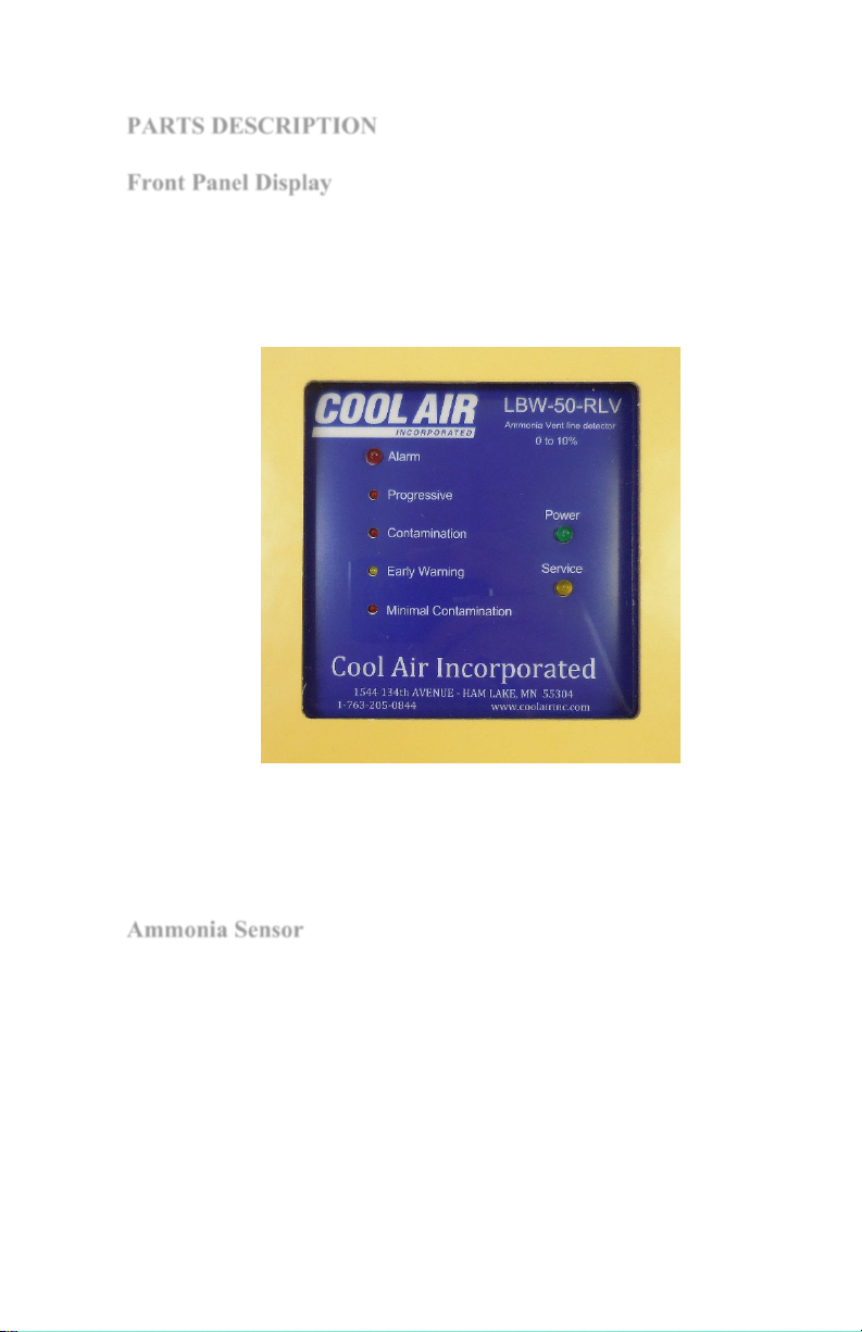
FRONT PANEL DISPLAY ..................................................................................6
AMMONIA SENSOR ..........................................................................................6
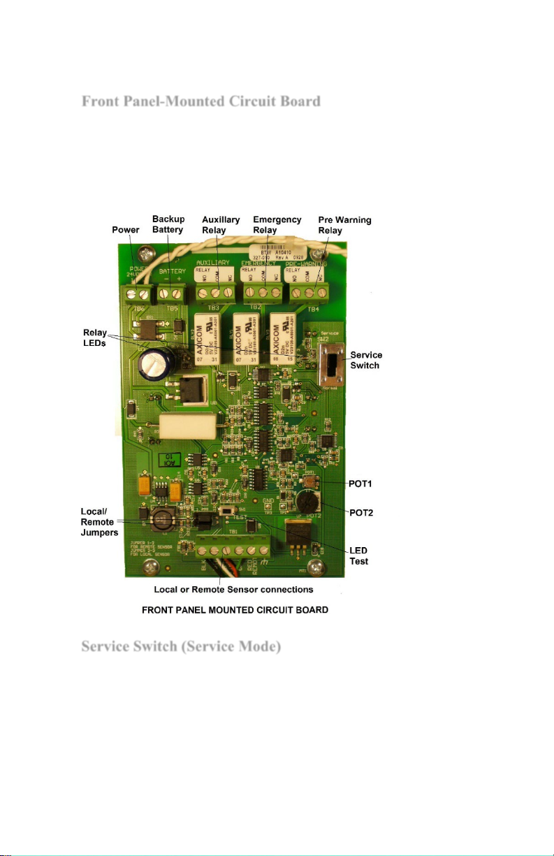
FRONT PANEL-MOUNTED CIRCUIT BOARD ....................................................7
SERVICE SWITCH (SERVICE MODE)................................................................7
ADJUSTABLE ALARM POTENTIOMETER..........................................................8
LED TEST BUTTON.........................................................................................8
LOCAL/REMOTE JUMPERS..............................................................................8
RELAY LED’S.................................................................................................8
ENCLOSURE-MOUNTED CIRCUIT BOARD .......................................................8
RELAYS ...........................................................................................................9
RELAY STATUS LEDS...................................................................................10
EXTERNAL CONNECTIONS ............................................................................10
WIRING DIAGRAM:.......................................................................................11
INSTALLATION AND SETUP................................................................. 13
REMOTE SENSING .........................................................................................15
REMOTE ALARM INSTALLATION ..................................................................15
AMMONIA LEAK INDICATION .......................................................................16
TESTING AND CALIBRATION ..............................................................16
TESTING.....................................................................................17
CALIBRATION ..........................................................................17
TECHNICAL SUPPORT ........................................................................... 18
WARRANTY................................................................................................ 19
LBW-50 SPECIFICATIONS ..................................................................... 20

LBW-50-RLV-%
Page 4
Rev. 1.0 10/14/2022
Copyright © 2022 by Cool Air Incorporated. All rights reserved.
IMPORTANT READ THIS FIRST
PLEASE READ AND UNDERSTAND THIS SECTION
BEFORE INSTALLING AND OPERATING THE LBW-50
DETECTOR
CAUTION:
Operating the detector in lower temperatures will slow the detector
response rate, and high humidity or excessive heat can cause the
“Minimal Concentration” LED to light.
After applying power, test the detector to ensure it is operating
correctly. Be sure the detector has been powered on for at least 20
minutes before testing.

LBW-50-RLV-%
Page 5
Rev. 1.0 10/14/2022
Copyright © 2022 by Cool Air Incorporated. All rights reserved.
INTRODUCTION
The Cool Air Incorporated LBW-50-RLV-% is an AC/DC powered
state-of-the-art ammonia leak detector that detects and indicates
ammonia concentrations of .1% to 10%. It comes equipped with a
catalytic bead, long-life ammonia sensor that has a quick and accurate
response to ammonia concentrations.
Outputs are three dry contact relays.
STANDARD FEATURES
The LBW-50-RLV-% comes with these additional standard features:
•Adjustable Alarm set point.
•Normally open, normally closed contacts for communicating
with common industry alarm systems.
•A NEMA 4X, UL-listed enclosure.
•Spare contacts for operating auxiliary equipment such as
exhaust fans, king valves, compressors, and additional
alarm systems.
•Service mode which allows for testing and calibrating
without setting off the alarms.

LBW-50-RLV-%
Page 6
Rev. 1.0 10/14/2022
Copyright © 2022 by Cool Air Incorporated. All rights reserved.
PARTS DESCRIPTION
Front Panel Display
The front panel display is comprised of a series of labeled indicating
LED’s. The LEDs provide an indication of ammonia concentration,
alarm status, power supply, and service mode at a glance.
For information on how the display indicates ammonia
concentrations, see the sections on ammonia leak indication
.
Ammonia Sensor
The detector comes with a catalytic bead, long-life sensor that has a
high sensitivity to amine compounds and a quick response to
concentrations of ammonia.
If a new ammonia sensor is installed, the detector must be re-
calibrated. See the “TESTING AND CALIBRATION” section.

LBW-50-RLV-%
Page 7
Rev. 1.0 10/14/2022
Copyright © 2022 by Cool Air Incorporated. All rights reserved.
Front Panel-Mounted Circuit Board
The front panel-mounted circuit board contains the controls necessary
for adjusting and operating the detector. Each control is described in
detail in the following pages. When the detector enclosure is open,
this circuit board is on the left, attached to the front panel.
Service Switch (Service Mode)
The detector can be set to one of two modes: normal operating mode
or service mode. The detector is in normal operating mode when the
service Switch is in the “Normal” position. When the service switch
is in the “Service” position, the detector continues to function as
usual, however the alarm, pre-alarm, and auxiliary relays are
disabled. This allows the detector to be serviced, tested, and
calibrated without tripping the alarm relays and setting off the alarms.

LBW-50-RLV-%
Page 8
Rev. 1.0 10/14/2022
Copyright © 2022 by Cool Air Incorporated. All rights reserved.
NOTE: When the detector is in the service mode, the
“Service” LED on the front panel flashes yellow. After 30 minutes in
service mode, the “Minimal Contamination” and “Early Warning”
LEDs will also be lit. This is done as a reminder to set the service
switch back to the “Normal” mode.
Adjustable Alarm Potentiometer
There is one adjustment potentiometer that is provided to set the
Alarm set point. The Pre-Alarm (Early Warning) is adjusted at the
factory. The Alarm set point is also pre-set at the factory but is field
adjustable. The adjustment procedure is in the “INSTALLATION
AND SET-UP” section.
LED Test Button
Pressing the momentary LED Test button will cause all LEDs to light
to up and all three relays to de-energize to confirm that they are
functional. This also allows testing of connected devices with out the
need to expose the sensor to ammonia gas.
Local/Remote Jumpers
JMPR1 and JMPR2 are not used in this device and must connect pins
2 to 3, the far-right position.
Relay LED’s
Two green LEDs indicate that the relays are energized. LED 9, to the
left of the relays, indicates that Alarm and Auxiliary relays are
energized. LED 10, to the right of the relays indicates that the Pre-
Warning relay is energized.
Enclosure-Mounted Components
The enclosure-mounted components include an AC to DC converter
for 100 to 240 VAC, 50/60 Hz operation. An optional back-up
battery can be installed in the location shown and wired to the front-
panel circuit board “Battery” terminal.

LBW-50-RLV-%
Page 9
Rev. 1.0 10/14/2022
Copyright © 2022 by Cool Air Incorporated. All rights reserved.
Power Supply
WARNING: RISK OF ELECTRIC SHOCK. DO NOT
REMOVE COVER. NO USER SERVICEABLE
PARTS INSIDE. REFER TO QUALIFIED SERVICE
PERSONNEL.
AVIS: RISQUE DE CHOC ELECTRIQUE. NE PAS
ENLEVER LE COUVERCLE. AUCUN ENTRETIEN
DE PIECES INTERIEURES PAR L'USAGER.
CONFIER L'ENTRETIEN AU PERSONNEL
QUALIFIE.
Power for the LBW-50 must be a nominal 100 to 240 Volts AC,
50/60 Hz, 16 VAC, or 24 VDC. The 100 to 240 Volts AC power is
connected to the AC to DC converter mounted on the back panel of
the enclosure. The 16 VAC or 24 VDC power is connected directly
to the “Power” terminals on the upper left-hand corner of the front
panel mounted circuit board. A safety ground terminal is also
provided on the back panel.
Relays
The detector has three miniature printed circuit board relays: The
Alarm, Pre-Alarm (Early Warning), and the Auxiliary relays. The
Auxiliary relay operates at the same time as the Alarm relay. In the
normal operating mode, the relays are energized in a normally open
state. If a loss of power to the detector occurs, the relays will de-
energize and the alarms, if connected, will activate.
Indice
Altri manuali Cool Air Sensore di sicurezza


