
Cooper Menvier SD3 Istruzioni operative

CONTENTS
INTRODUCTIONINSTALLATIONCOMMISSIONINGOPERATION
1
Contents
Introduction 2
Main features ..........................................................................................3
Specifications .........................................................................................4
SD3 panel layout .....................................................................................4
Installation 5
General ..................................................................................................5
Mounting instructions ..............................................................................5
SD3 internal board layout ....................................................................... 5
Control panel (SELV) connections ........................................................6
Telephone (TNV) connections ..............................................................7
GSM module installation ..........................................................................8
GSM module operation ................................................................. 10
Commissioning 11
Getting started .....................................................................................11
Using the programming menu .............................................................. 12
Accessing the programming menu .................................................... 12
Exiting from the programming menu ..................................................12
Programming menu options ..............................................................12
Basic setup .......................................................................................12
Programming menu options list .............................................................13
Contact Details .................................................................................. 14
Messages ........................................................................................15
Voice messages ............................................................................15
Text messages .............................................................................. 16
System Options ................................................................................. 17
Trigger Polarity ..............................................................................17
Remote Options ............................................................................17
SMS Options .................................................................................18
Display Options .............................................................................18
Alarm Levels ..................................................................................19
Record Options .............................................................................19
Report Options ..............................................................................19
Line Priority ...................................................................................19
Access Codes ...................................................................................20
Acknowledgement and Abort Options ..............................................21
HL
Abort Options ................................................................................21
Clear by Options ........................................................................... 21
Outputs ............................................................................................. 22
Call Routing Options .........................................................................23
Set Date and Time ............................................................................23
View Log ........................................................................................... 24
Test Options ......................................................................................25
Test Messages .............................................................................. 25
Test Outputs .................................................................................26
Test Triggers ..................................................................................26
Test Line ........................................................................................ 27
Test Supply ................................................................................... 27
GSM Phone Utilities ......................................................................27
Software Version ...........................................................................28
Operation 29
How to acknowledge a voice message .................................................29
Aborting an alarm call ............................................................................ 29
Recording and playing a memo locally .................................................. 29
Using the remote access feature ...........................................................30
Remote access by dialling in ............................................................. 30
Remote access via an alarm call ........................................................ 30
The remote access menu ..................................................................31
Toggle outputs ..................................................................................31
Listen-in & talkback mode .................................................................31
Testing triggers remotely .................................................................... 32
Entering contact numbers remotely ................................................... 32
Remotely recording and playing messages ........................................32
Alarm voice and restore messages ................................................32
Memo messages ...........................................................................32
Text Editing Keys .................................................................................. 33
Declaration of Conformance .................................................................. 34
CONTENTS
INTRODUCTION
INSTALLATIONCOMMISSIONINGOPERATION
2
Introduction
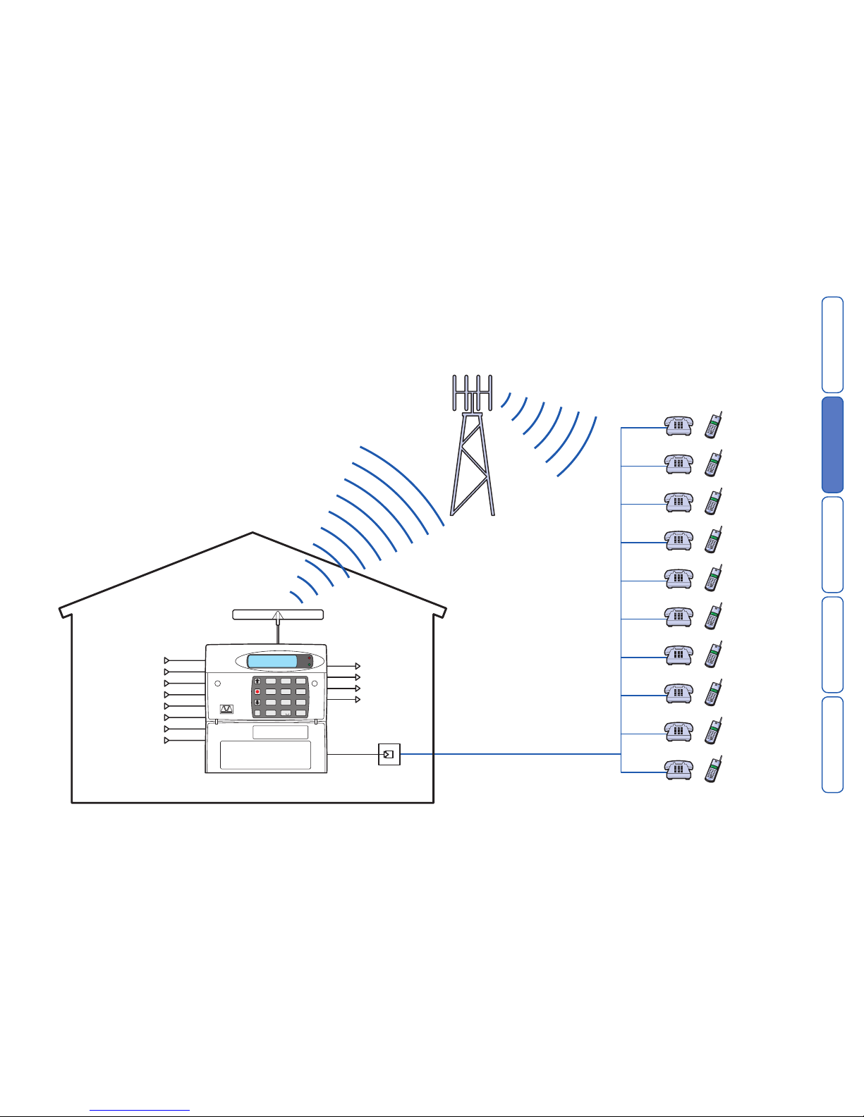
The SD3 Speech Dialler provides a means of communicating information to fixed
and mobile telephones. You can either connect the SD3 to an alarm control panel
(taking advantage of its power supply and battery backup) or use the SD3 in a
standalone role.
HL
OP1
OP2
3
6
9
ESCENT
Clear
2
5
8
0
1
4
7
def
mno
wxyz
abc
jkl
tuv
ghi
pqrs
SD3 +24°C
12:01 06Jul06
Trigger input A Output 1
Contact 1
Contact 2
Contact 3
Contact 4
Contact 5
Contact 6
Contact 7
Contact 8
Contact 9
Contact 10
or
or
or
or
or
or
or
or
or
or
Output 2
Output 3
Output 4
Trigger input B
Trigger input C
Trigger input D
Trigger input E
Trigger input F
Trigger input G
Trigger input H

CONTENTS
INTRODUCTION
INSTALLATIONCOMMISSIONINGOPERATION
3
Main features
Triggers
The SD3 has eight trigger inputs and you can assign a voice message and/or a
text message to each input. The unit can also send a voice message and/or a text
message when the triggers have been restored.
For most applications you would normally connect the trigger inputs to the com-
municator outputs (or bell output) of an alarm control panel. However, you can also
connect other devices, such as smoke detectors or temperature sensors directly
to the trigger inputs. The unit allows you to program the polarity of the trigger
inputs as either positive or negative applied/removed.
Contacts
The SD3 allows you to store up to 10 contacts: you can assign each one a name,
telephone number, message type, and acknowledgement type.
IMPORTANT: DO NOT use the SD3 to call the Police via the emergency services
phone numbers.
Voice Messages
The SD3 has a built-in microphone and speaker to allow you to record and replay
audio messages directly from the unit.
The SD3 can store up to eight separate alarm messages, eight restore alarm mes-
sages (a different message can be sent when the trigger event has been removed)
and one common message (normally used to store the name and address of the
premises). Each message can be up to 30 seconds in length.
Text Messages
The SD3 can also send text messages to mobile telephones using the SMS text
service (Short Message Service). The unit does this by calling a SMS service cen-
tre, which takes the text message from the SD3 and forwards it to the contact’s
mobile telephone. The unit can store eight separate 40-character alarm messages,
eight 40-character restore alarm messages (a different message can be sent when
the trigger event has been removed) and one common message (normally used to
store the name and address of the premises). When the unit sends a text mes-
sage, it adds the alarm message to the site details message.
Acknowledgement
On receiving a voice message call from the SD3, the contacted person can ac-
knowledge it at any time by pressing 8 on their telephone. If the contact does not
acknowledge the voice message then the SD3 repeats the message several times,
after which the unit abandons the call and dials the next available contact.
Call-Abort
The SD3 has several call-abort options, which include restoring the trigger input or
entering the user code. When the unit has aborted a call it immediately shuts down
and returns to its normal standby mode.
Outputs
The SD3 has four programmable outputs that you can use to indicate the status
of the unit. You may also program the outputs for remote control. For example,
you could use this facility to remotely turn outputs on and off with a touch-tone
telephone.
Temperature sensor
The SD3 displays the current ambient temperature. You can program temperature
high and low alarms, linking them to two corresponding output types.
Time and date
The unit contains an internal clock which can display the current time and date.
In addition, the time and date will be added to text messages and trigger events,
thus providing a useful audit trial in the log.
Please note that the time and date feature is designed as a guide.
Listen-In Mode
The SD3 has a listen-in mode, which switches an internal microphone to the tel-
ephone line so that you can hear activity at the protected site.
The contact can activate the listen-in mode at the time of receiving a voice mes-
sage or by calling into the SD3 and using the Remote Access feature.
Talkback Mode
The SD3 has a talkback mode, which switches the internal loudspeaker to the tel-
ephone line so that you can talk to the protected site. The contact can activate the
talkback mode at the time of receiving a voice message or by calling into the SD3
and using the Remote Access feature.
Message
The SD3 allows you to record short audio messages, either locally at the unit, or
remotely, using a touch-tone telephone. After recording a new message the unit
will indicate it on the display and can optionally give a beep. You can also program
the message feature to record when a trigger input is activated.
Remote Access
If you enable this feature you can access the SD3 remotely by dialling into the unit
with a touch-tone telephone. Once connected you can turn on and off the four
outputs, activate the listen-in/talkback mode, listen to the message, record a new
message, leave a memo, carry out test triggers or record telephone numbers.
CONTENTS
INTRODUCTION
INSTALLATIONCOMMISSIONINGOPERATION
4
Specifications
Supply voltage: 10.5 - 28VDC
Current consumption (@12VDC): 50mA (Standby), 170mA (Active)
Trigger Inputs: Eight: positive/negative applied or
positive/negative removed (5 - 24VDC)
Outputs: X4 Open collector switched
-ve @100mA
Telecommunications Approval: CTR21
REN Rating: 1
Dialling Formats: DTMF
Dimensions: 140mm x 115mm x 30mm
Weight: 360g (approximately)
Operating environment: -10oC to +55oC
SD3 panel layout
Keypad function keys
A Scroll up
B Record / special character key
C Scroll down
D Clear display
E Enter / Play
F Escape
OP1
OP2
3
6
9
ESC
ENT
Clear
2
5
8
0
1
4
7
def
mno
wxyz
abc
jkl
tuv
ghi
pqrs
SD3 +24°C
12:01 06Jul06
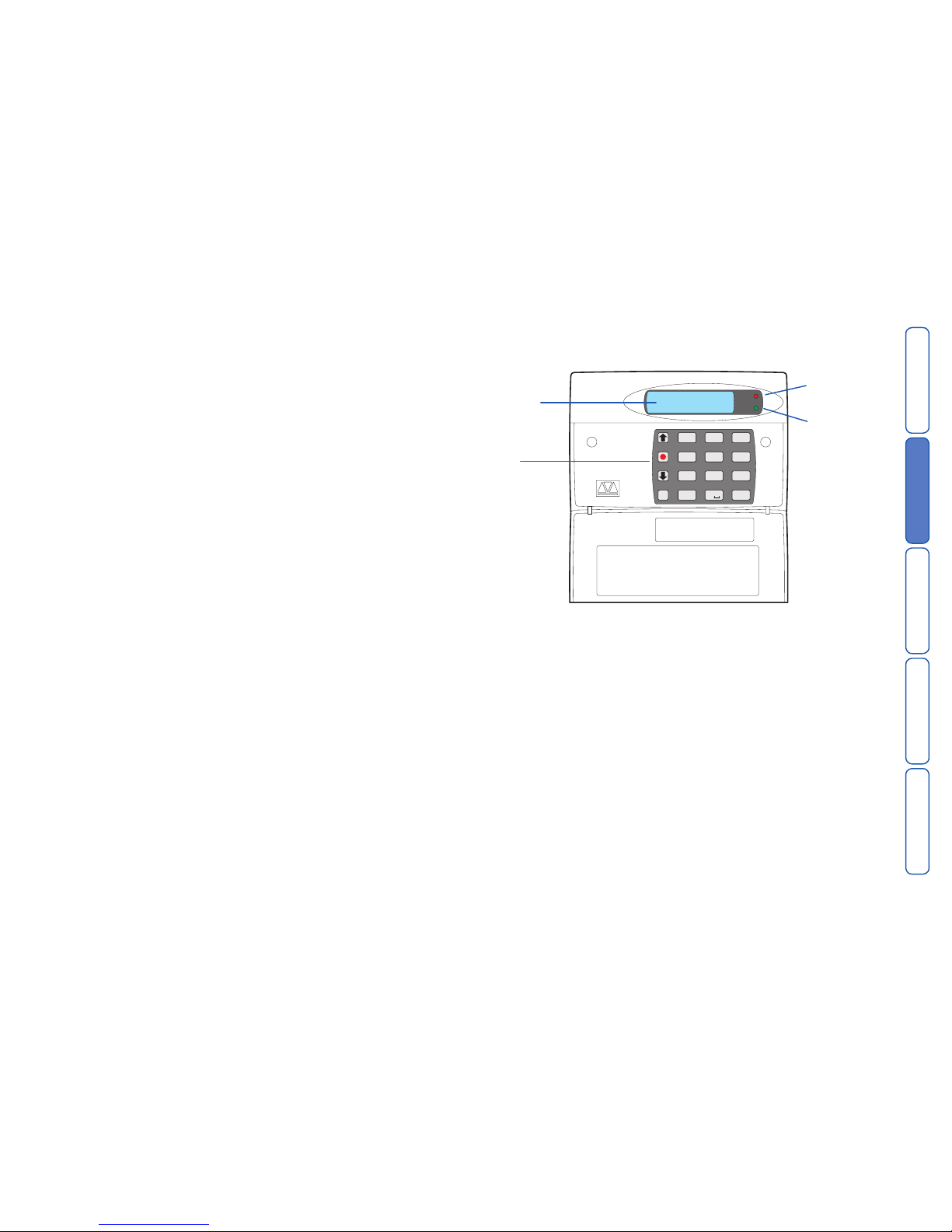
Two-line backlit
LCD display
Keypad
Red indicator
shows the sta-
tus of Output 1
Green indicator
shows the sta-
tus of Output 2
CONTENTSINTRODUCTION
INSTALLATION
COMMISSIONINGOPERATION
5
Installation
General
The SD3 is designed to connect to an intruder alarm control panel or similar.
The SD3 requires a power input (from an alarm control panel or separate power
supply) of between 10.5V and 28V, with a supply capability of 100mA or greater.
The SD3 is supplied with a 2-metre telephone lead, which plugs directly into any
standard BT socket. Cooper Security recommends that you site the unit as near to
a BT telephone socket as possible. If this it not possible you should either obtain
an approved BT extension lead or permanently wire the unit to the BT socket (see
‘Connections to the telephone line’).
Mounting instructions
1 Separate the cover from the base by using a screwdriver to carefully push two of
the retaining clips (top or bottom) inwards from the base indents.
2 Remove the cover assembly and store in a safe place.
3 Hold the base in position (keyhole to the top) and mark the three securing holes.
Remove the base then drill and plug the holes.
4 Pass all cables into the base through the cable entries and then secure the base to
wall.
HL
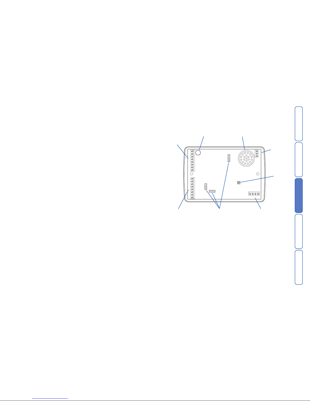
SD3 internal board layout
Connection types and standards
The SD3 connection terminals contain a mixture of alarm system-related connec-
tions and telecommunication connections. The alarm-type connections are termed
Safety Extra Low Voltage or SELV, while the telecommunication connections are
called Telecommunications Network Voltage or TNV.
Note: It is vitally important that the two types of connections are kept separate
and only linked to appropriate external alarm systems and telephone connections,
respectively.
TNV circuits should only be connected by a qualified person in accordance with
local regulations.
G
E
A
A
H
F
B
B
C
A1
D
B1
12V 0V OP1
TAMPER OP2 OP3 OP4
TRIG
TRIG
TRIG
IN 0V OUT
LINE
MicrophoneUpper connector
for input triggers
and tamper wiring
Lower connector
for input triggers,
power supply, and
output wiring
GSM module sockets
Line
connector
Back
tamper
switch
Sounder/loudspeaker
Telephone
line
connector
CONTENTSINTRODUCTION
INSTALLATION
COMMISSIONINGOPERATION
6
Control panel (SELV) connections
Before making any connection to the SD3 isolate ALL power from the control
panel (mains and battery). Do not continue if there is power still present
on the control panel.
+12V & 0V
Connect these terminals to the 12V auxiliary power supply of the alarm control
panel or to a stand-alone power supply, if necessary.
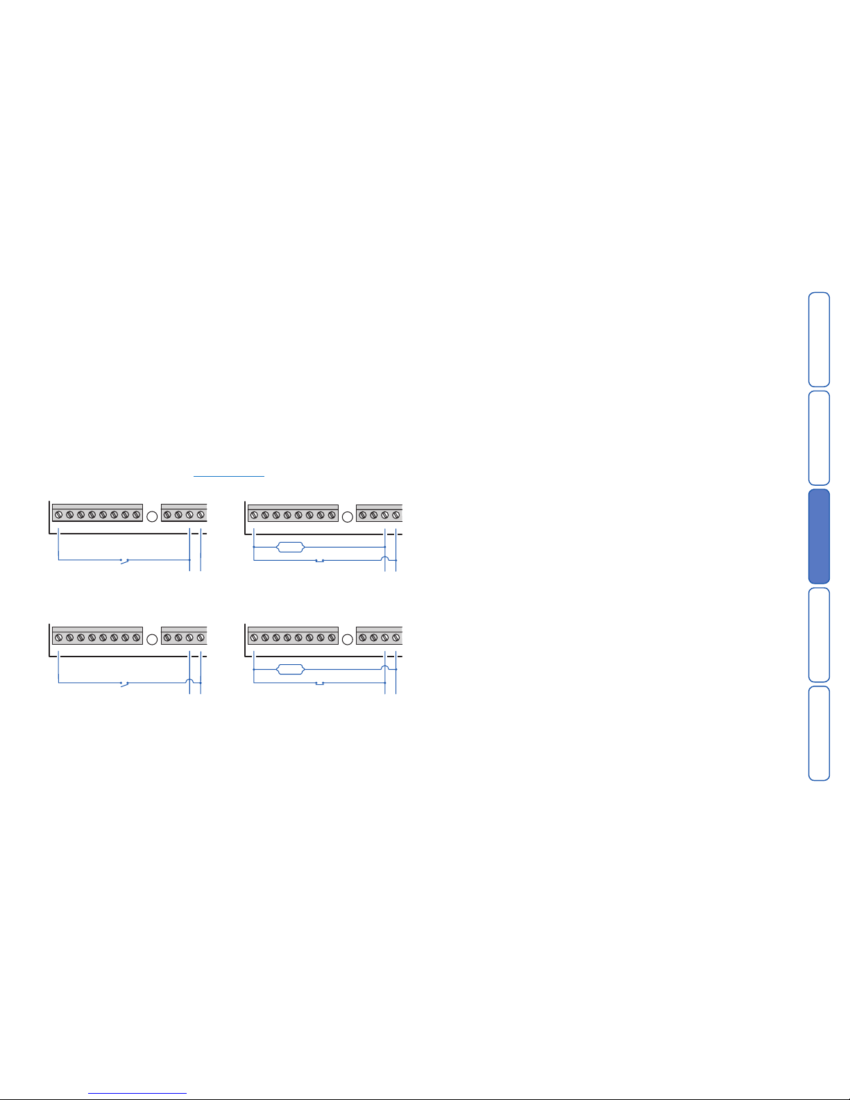
Trigger inputs (A to H)
Connect these terminals to the relevant outputs on the alarm control panel. When
an alarm panel triggers an input, the SD3 initiates the calling sequence and plays
the relevant speech and/or text message. The diagrams below show the various
wiring options for the trigger inputs.
Note: All inputs must use the same trigger input polarity. The chosen polarity is be
selected within System Options > Trigger Polarity.
Trigger input connections for positive operation
Trigger input connections for negative operation
Tamper
These terminals provide tamper protection for the SD3 and should be connected
to the auxiliary tamper circuit on the alarm control panel.
OP1 to OP4
Four programmable switched negative @100mA outputs.
Control Panel Connection Table
The table below shows connection details for various alarm control panels:
Control panel Trigger inputs 12V 0V
A B C Trigger
Fire PA Intruder polarities
ADE Accenta 6 N/A N/A B -ve 13V+ 13V-
ADE Concept 6 N/A N/A B -ve 13V+ 13V-
ADE Optima 6 N/A N/A B -ve 13V+ 13V-
ADE Optima XM N/A N/A B -ve 13V+ 13V-
C&K 800L N/A N/A S- -ve Aux + Aux -
CQR Premier 9 FA* PA IA +ve Aux 12V Aux 0V
DA Abacus 6 N/A N/A Bell -ve +12V -0V
DA Abacus 8 N/A N/A Bell -ve +12V -0V
Gardtec 500 Series N/A N/A Bell- -ve 12V 0V
Gardtec 800 Series D1* PA 12Hr -ve 12V 0V
Menvier TS400/410 Cct 4 Cct5 ALM -ve Aux + Aux -
Menvier TS Range Comm. 1 Comm. 2 Comm. 3 -ve Aux + Aux -
Pyronix Octagon N/A PA ALM -ve Aux + Aux -
Pyronix Conqueror N/A N/A BA -ve Aux + Aux -
Scantronic 9448 N/A COM 2 COM 3 -ve 12V 0V
Scantronic 9X5X Series Pin 1 Pin 2 Pin 3 -ve Pin 9 Pin 10
Texecom Veritas 8/R8/ N/A N/A B -ve Aux + Aux -
Texecom Veritas R8 Plus Com1 Com2 Com3 -ve Aux + Aux -
Texecom Veritas Excel Com1 Com2 Com3 -ve Aux + Aux -
Texecom Premier 48/88/168 Digi1* Digi2* Digi3* -ve Aux + Aux -
*Control panel output may require programming to the correct function.
GEAHFB C D 12V 0VTAMPER
TRIGTRIGTRIG
to 12V
supply
normally
open
loop
GEAHFB C D 12V 0VTAMPER
TRIGTRIGTRIG
to 12V
supply
normally
closed
loop
1kΩ
GEAHFB C D 12V 0VTAMPER
TRIGTRIGTRIG
to 12V
supply
normally
open
loop
GEAHFB C D 12V 0VTAMPER
TRIGTRIGTRIG
to 12V
supply
normally
closed
loop
1kΩ
CONTENTSINTRODUCTION
INSTALLATION
COMMISSIONINGOPERATION
7
Telephone (TNV) connections
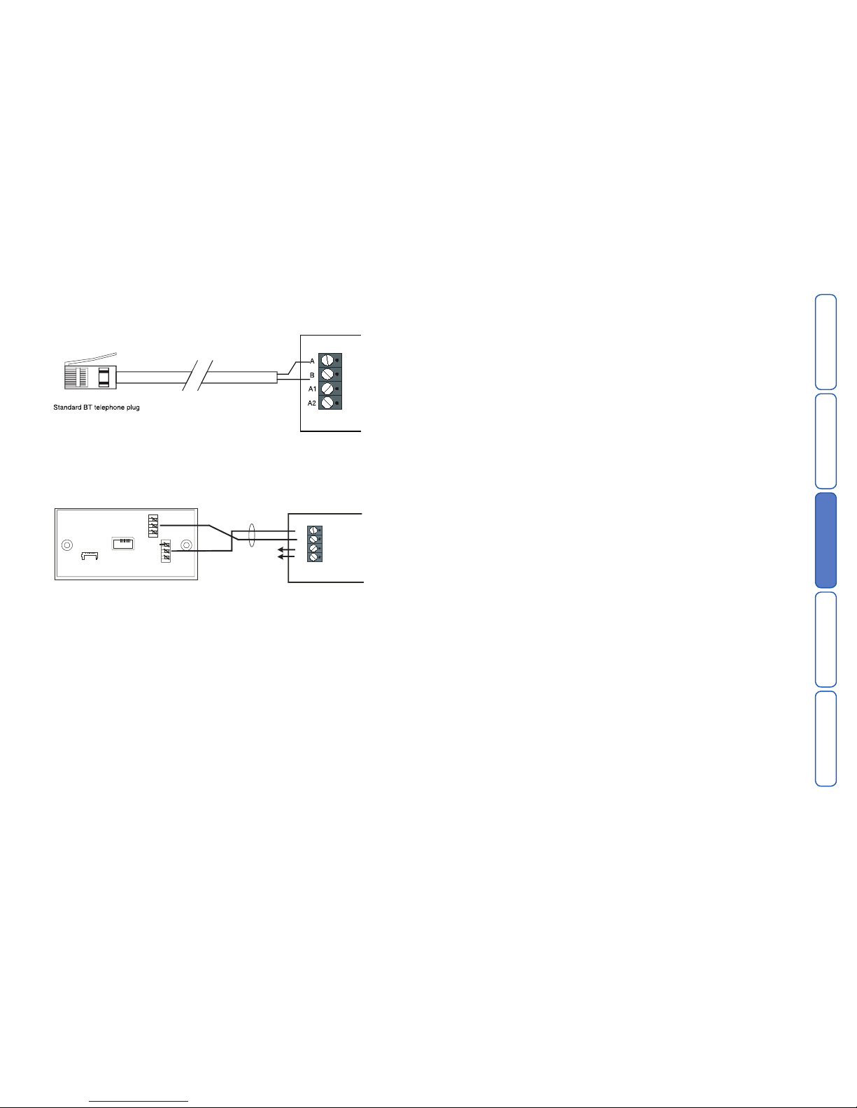
The easiest way to connect the SD3 to the telephone line is to use the telephone
lead that is provided with the unit as shown below:
3
2
1
6
5
4
A
B
A1
B1
Cable type 1/0.5 CW1308
BT Master Jack (NTE5)
User accessible connections
To other telephone
extension sockets
However, if the lead is not long enough or a serial connection is required the SD3
can be hard wired to the telephone socket as shown below:
CONTENTSINTRODUCTION
INSTALLATION
COMMISSIONINGOPERATION
8
GSM module installation
The GSM module is a plug-in board for the SD3 Speech Dialler that allows it to
communicate via a mobile phone network. In addition, the GSM module allows the
SD3 to send SMS (Short Message Service) text messages.
This section provides brief instructions on fitting the GSM module within the SD3.
To prepare the SD3 to use the GSM module, please see the programming section
later in this guide.
Note: If you are adding the GSM module to an SD3 that has already been installed
then first make sure that the system is completely unset and in its programming
mode (to prevent the control unit raising un-necessary tamper alarms when you
open the case.)
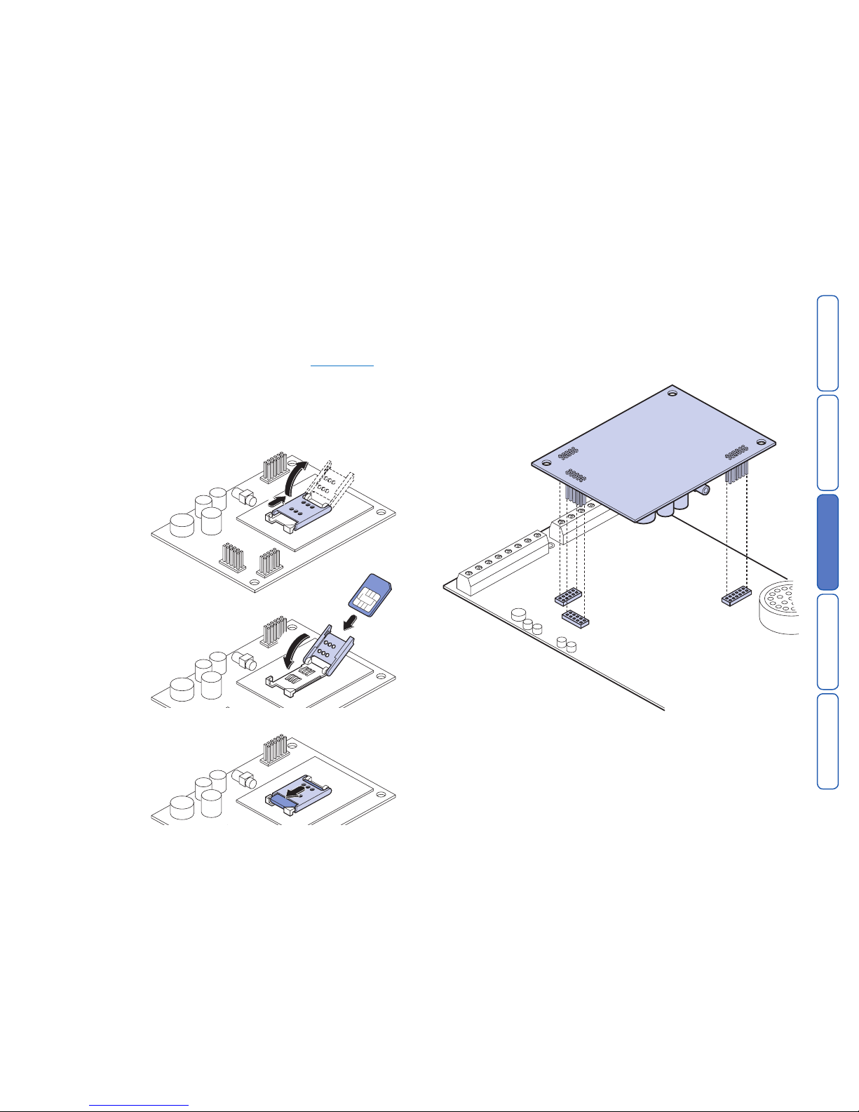
To install the GSM module
1 Unpack the GSM module and its antenna.
3 If necessary, remove the SD3 unit from the wall fixings and remove the two
screws holding the front panel and backbox together.
4 Separate the SD3 front panel and backbox, and disconnect the power connec-
tion and the siren lead (if fitted).
5 Fit the GSM module to the sockets on the SD3 circuit board.
2
1
1
2
2 Fit your SIM card into
the SIM holder of the
module as shown
here. Double check
that you have fitted the
SIM card in the correct
orientation.
CONTENTSINTRODUCTION
INSTALLATION
COMMISSIONINGOPERATION
9
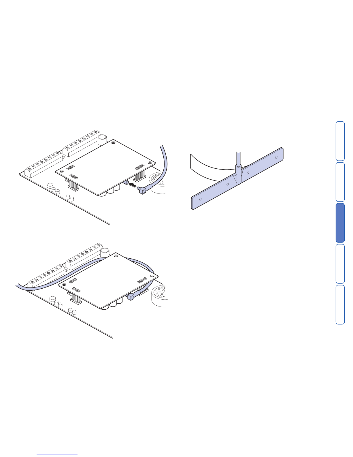
6 Thread the antenna cable through the backbox and connect it to the antenna
input socket on the GSM module.
7 Feed the antenna cable around the top and side of the module. Take care not to
unseat the antenna connector from the socket as you route the cable.
8 Using the supplied surface wipe, clean the area onto which you intend to stick
the antenna.
9 Remove the backing paper on the glued side of the antenna. Fix the antenna
onto the cleaned surface. Note: The adhesive on the antenna is fast acting. You
will not be able to reposition the antenna once you have put it in place.
10 Re-connect all previously removed connections (including power).
11 Re-attach the SD3 panel onto the backbox and refit the two screws holding the
case together.
12 Re-attach the combined unit to the wall fittings.

CONTENTSINTRODUCTION
INSTALLATION
COMMISSIONINGOPERATION
10
GSM module operation
To use GSM module features
1 Apply power to the SD3 unit.
2 From standby, enter the user code, then use the scroll keys (A or C) or 0 to
display the Test Options menu:
Test Options
Press E to select. The screen will show the first option: Test Messages.
3 Press C or press 6 to show: GSM Phone Utils.
4 Press E to select. The screen will show the first option: Make Call.
5 Use the scroll keys (A or C) and then E, to select the following options:
Make Call Allows you to enter a number and make a call via the
GSM link. The SD3 will act like a hands free mobile
phone.
Signal Strength If the level is low you may need to reposition the con-
trol unit, or seek another service provider.
GSM Number (This may not appear if you are using Vodafone as a
service provider.) Note this number down so that you
can supply it when registering your SIM card.
IMEI Number You should note this number down as you will need
to provide it when you register your SIM card with
certain service providers.
To register your SIM card
Once you have fitted the GSM module and its SIM card, you must register the
SIM card with the service provider. To do this you must make a telephone call
from the SD3 control unit via the newly installed GSM module.
1 Using the method discussed above, select the Make Call option.
3 Dial the appropriate telephone number for registering the SIM card as shown in
the instruction leaflets for the card. (See below.)
Note that the SD3 cannot support the text message response service calls using
the * and # keys. You must call the service provider manually and either register
with a human operator, or navigate an automated answering service. Once the
phone call is established you can use the * and # keys as you would on a normal
phone.
The exact details of registering your SIM card differ for each provider. The follow-
ing sections show hints for the main providers.
O2
Note that 02 print the SIM serial number and the GSM telephone number on the
packing for the SIM card.
To register an 02 SIM dial 248 and follow the instructions given by the automatic
answering service.
T-Mobile
T-Mobile print the GSM telephone number, PIN number and PUK (unlock number)
on the sheet carrying the SIM card and top up card.
To register a T-Mobile SIM dial 150 and follow the instructions given by the auto-
matic answering service.
If you have several mobile phones fix the sticky label provided showing the GSM
number to the top up card.
Orange
Make sure you have the GSM module’s IMEI number to hand. You will also need
the SIM card serial number which is printed on the SIM card.
You will need to provide a password and the four digit code to identify yourself
in the future. Choose them before making the call and write them down in the
booklet.
To register an Orange SIM dial 0800 079 0006. A human operator will reply.
While registering your SIM, the operator will provide you with your GSM number.
Make sure you note this number on the top up card.
Vodafone
To register a Vodafone SIM dial 2345 and follow the instructions given by the
automatic answering service. During the instructions you will be given your GSM
number. Make sure that you note this number down on the back of the top up
card.
Using top up cards
Each of the service providers listed in the previous instructions supply top up
cards with their SIMs. Part of the registration procedure is to link the top up card
with the SIM. The cards contain just enough credit to allow you to make the
registration call. Once you have finished this process you will need to supply more
credit to the top up card. You should do this immediately.
While registering, make sure that you write the phone number of the GSM module
down on the top up card.
The table below provides spaces for you record the relevant information about
your GSM installation.
IMEI No. .....................................................................................
SIM Card Serial No. ....................................................................
GSM No. ....................................................................................
Top Up Card No. ........................................................................
Indice


