Cotes CR300 Guida rapida

INSTALLATION AND INSTRUCTION MANUAL
FOR CR300 DEHUMIDIFIER.
PRODUCTION NUMBER :
STOCKNO. 100063
DOCUMENT NO.: 300-04E
PAGE CONTENTS :
1 1. Principle of operation
3 2. Applications
4 3. Dimensions, inlet- & outlet diagram
5 4. Technical data
7 5. Components diagram
8 6. Capacity diagram
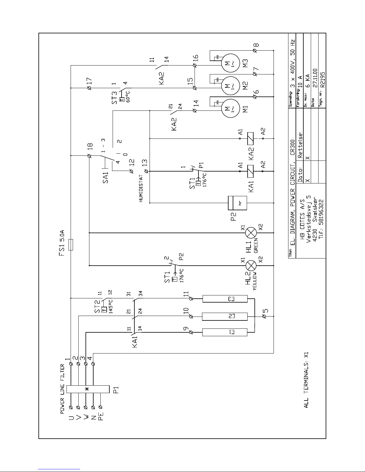
7. Electric features :
9 7.1 Power and control circuit diagram
10 7.2 Wiring in el-box
11 7.3 Wiring in cabinet
12 7.4 Placing of components in el-box
13 7.5 Electric components
13 7.6 Indicator neon
14 7.7 Connection of hygrostat
14 7.8 Electric connection
14 8. Installation
16 9. Fan curves/external pressure
15 10. Start-up procedure
18 11. Maintenance
19 12. Trouble shooting
20 13. Service/repair
13.1 Safety instructions
13.2 Replacing of electric components in
the E-box.
13.3 Replacing of gear motor, reg.air fan,
thermostats ST3
13.4 Replacing of process. air fan.
13.5 Replacing of heating elements
13.6 Replacing of rotor, gaskets, drive-
belts
21 14. Sound data
22 15. Reg. Duct set, standard.(option).
28.02.03
C TES HB COTES A S
HB DEHUMIDIFICATION SYSTEMS
Postgiro: 466-0722
CVR-nr./VAT-no.: 15 20 03 32
Bank: Danske Bank
Caspar Brands Plads 9, 4220 Korsør
Konto/Acc: 3212 3212298972
Swift: DABADKKK
Internet: www.hbcotes.com
E-mail: [email protected]
Værkstedsvej
DK- Skælskør
Tel +
Fax +
5
4230
45 58 19 63 22
45 58 19 58 44

Page 1
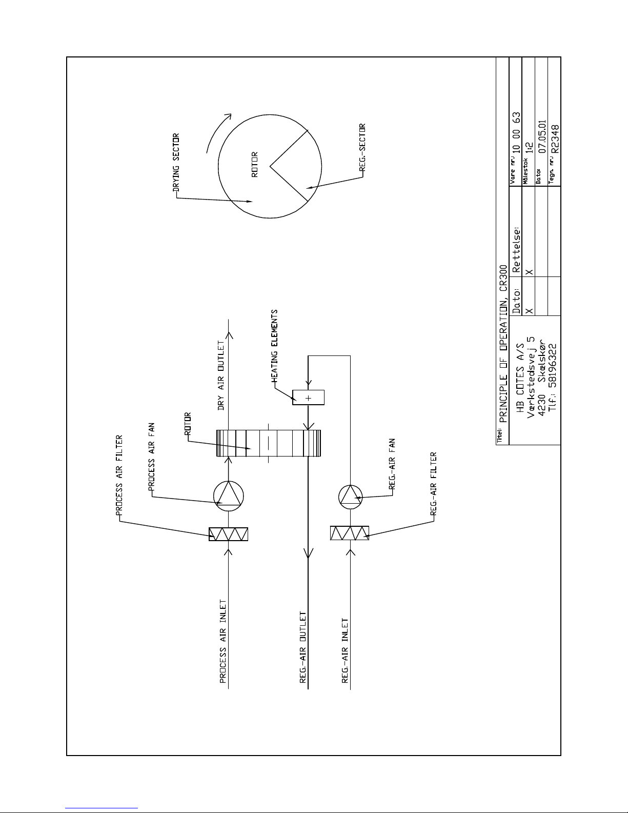
The dehumidifier removes water from an airflow through, and
the removed water is carried away from the dehumidifier with
the regeneration air (henceforward called reg.-air).
Water adsorption and -extraction takes place in an rotor made
of water resistant silica gel.
The airflows in the dehumidifier divides the rotor in two
parts : drying part and reg.-part.
Two separate air flows passes through the rotor:
- the main air (moist air inlet) goes through the drying
part, and leaves the dehumidifier as dry air
- the reg.-air coming from the reg.-air fan, passing the
electric heater and leaves the heater with a temperature
of 135C. This warm reg.-air now goes through the reg.-
part and the energy is used for evaporation of the adsorp-
ed water. This water vapour now leaves the dehumidifier
within the reg.-air. (see principle fig.1, page 2 ).
The two air flows are fixed and the rotor turns - this gives
an automatic process of simultaneous water adsorption and wa-
ter extraction.
The inlet conditions of the air to be dried, determines how
much water the dehumidifier will remove.
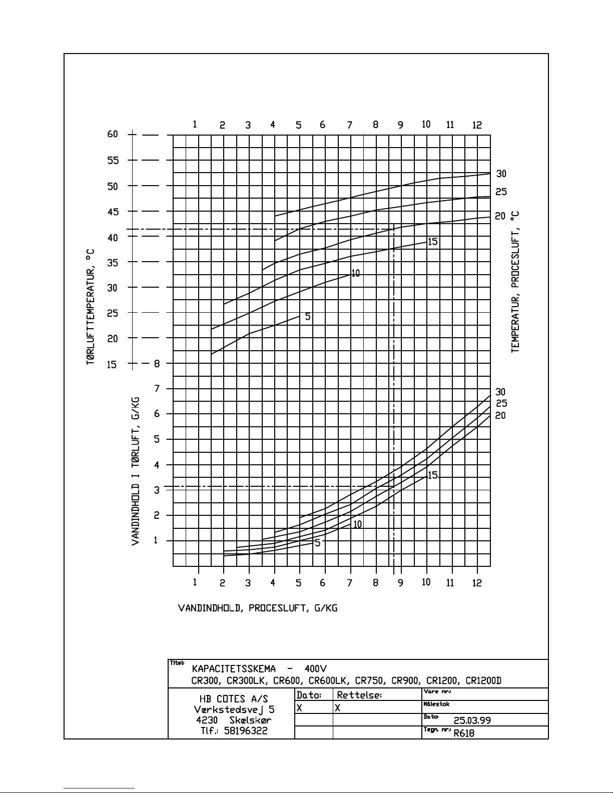
On page 8 the capacity diagram shows how much water will be
removed per kg air going through.
(shown in the diagram)
- inlet air conditions 20C, 60 %RH, gives water content 8,7
g/kg
- the diagram shows then dry air condition of X= 3,2 g/kg
- removed per kg air is then: 8,7 - 3,2 = 5,5 g/kg
Dry air flow is nominal 300 m3/h = (x 1,2) = 360 kg/h
Capacity, removed water per hour = 360 x 5,5 = 1980 g/h
= 47 kg/24h
- at 400V.
The temperature of the dry air is higher than for the inlet
air. This is caused by the evaporation heat release and heat
gain from the rotor. The temperature is shown to be 42C.
1. PRINCIPLE OF OPERATION.
CAPACITY DIAGRAM, R618.
Example:
Capacity CR300 at this condition:

Page 3
Dehumidifiers in the CR range is used for dehumidification
of ambient air at normal atmospheric pressure. This can be
an installation for moisture control in an unheated store
room, in a water work building, production room for hygro-
scopic materials... - with the dehumidifier in a separate
installation.
The dehumidifier also can be used as a part of a bigger air
treatment system. Here the dehumidifier often will be placed
in a by-pass to the main system.
In this case the pressure in the main system will influence
the dehumidifier - and your supplier must be contacted, as
this can influence the capacity of the dehumidifier.
Normally the dehumidifier will be placed in a wall bracket
or in a frame placed on the floor. Both parts can be sup-
plied as options.
The air to the dehumidifier should be free from solvents or
other explosive components, and should be free from pollu-
tion from solid particles and chemical substances ( ex.
acids, bases...).
- max. humidity ...................... 100 %RH
- max. temperature ................... 35C
- max./min. pressure ................. ambient +/- 300Pa
2. APPLICATIONS.
For air to the dehumidifier the following limit values
must be respected :
The CR range is for indoor, stationary installations.
Should not be placed in rooms with possibility for free wa-
ter on the cabinet.

Page 5.
Dry air, free blowing ............ : 410 m3/h
Dry air, nominal ................. : 300 m3/h
Reg.air, nominal ................. : 90 m3/h
External pressure, process air ... : 240 Pa at 300 m3/h
External pressure, reg.air ....... : 70 Pa at 90 m3/h
(see fan curves, page 15)
Capacity at 20C, 60 %RH .......... : 1,90 kg/h (at 400V)
(see capacity diagram page 8)
Power consumption, electric heater : 3000W, 230/400V
Process air fan .................. : 210W, 230V
Reg.air fan ...................... : 80W, 230V
Motor for gear ................... : 5W, 230V
Power consumption, total ......... : 3300W, 400V
Voltage .......................... : 380-400V, 3N+PE
External fuses ................... : 10A
Rotor ............................ : SG Ø300/100
Rotations of rotor ............... : 20/rph
Gear for rotor ................... : Saia J1M
Drive belt ....................... : Ø8/1070
Belt pulley ...................... : SPZ63-1
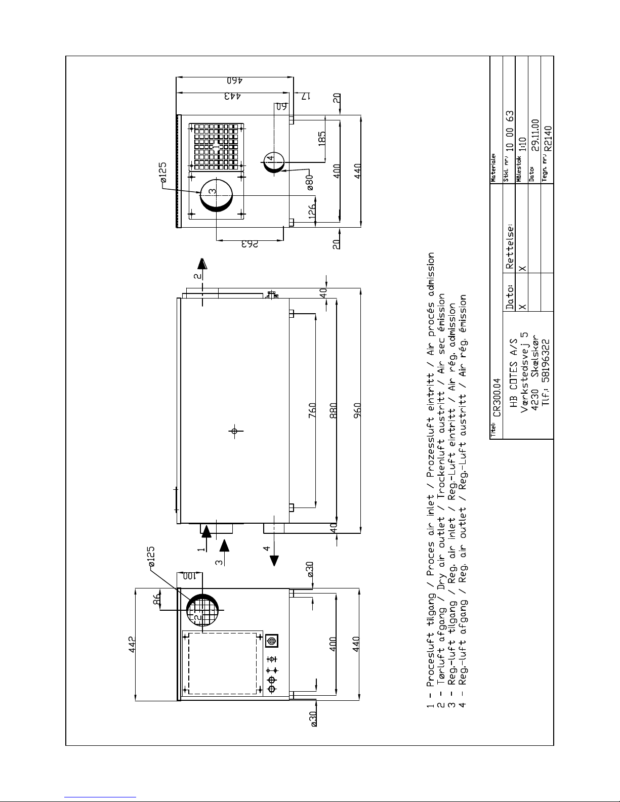
L x B x H ........................ : 880x440x460 mm
Weight ........................... : 45 kg
4. TECHNICAL DATA, CR300.
FURTHER SPECIFICATIONS:
DIMENSIONS, WEIGHT:


Page 7
1 1 121860 Cabinet part, back plate, removable
2 1 123003 Frame for fan and filter
3 1 123009 Cover for filter, removable
4 1 121843 Cabinet part, top cover, removable
5 1 127004 Pulley, SPZ63-1
6 1 132101 Drive belt, Ø8/1050
7 1 110412 Gear, Saia J30S
8 1 110400 Motor for gear, M3
9 1 130010 Gasket, Ø100/80, silicone rubber.
10 1 121854 El-Box, mounted with
11 1 all electric components
12 1 121858 Cover for El-box, removable
13 3 111417 El spiral heaters E1...E3
14 1 121844 Electric heater box
15 1 121810 Connector for reg.air inlet
16 5 120151 Distance bolt Ø12
17 1 124058 Rotor Ø300/100
18 1 121128 Connector for reg.air outlet
19 1 121841 Cabinet
20 1 130501 Flexible hose, Triapur P2PU Ø80
21 4 132004 Rubber "feets" ø30x15
22 1 120711 Reg.air outlet Ø80
23 1 123012 Reg.air inlet Ø80
24 1 130217 Filter cassette, 180x180x48, Reg.air
25 1 111773 Fan, reg. air, M2
26 1 130501 Flexible hose, Triapur P2PU Ø80
27 1 121842 Cabinet part, front cover, fixed
28 1 120713 dry air outlet, Ø125
29 1 121861 Dividing plate, for, fixed
30 2 131001 Teflon ring, Ø306
31 2 130100 Rubber profile for teflon ring
32 1 120150 Shaft for rotor
33 1 121172 Dividing plate, back, removable
34 2 131005 Teflon disc
35 1 111770 Fan, process air M1
36 1 130217 Filter cassette, 180x180x48, Process air
37 1 123011 Cover for process air
5. COMPONENTS LIST CR300.
(Ref to drawing no. R2141)
POS PCS ITEM NO. DESCRIPTION
Indice
Altri manuali Cotes Deumidificatore


