
Curtis 1620S Manuale utente

manual
MODEL
1620
SWITCH MODE
BATTERY CHARGER
Before charging, read
instructions carefully!
®
Applicable to 230VAC units only

IMPORTANT SAFETY INSTRUCTIONS
SAVE THESE INSTRUCTIONS
Read the Operating Instructions carefully before using the Model 1620 charger.
1. WARNING – Failure to install and operate the charger in accordance with these instructions may result
in damage to the charger or injury to the operator.
2. WARNING – Never place the charger directly above or below the battery being charged. Gases or fluids
from the battery will corrode and damage the charger. Locate the charger as far away from the battery
as the output cable allows.
3. WARNING – Explosive gases may result from charging. Provide adequate ventilation during charging.
Prevent flames or sparks.
4. WARNING – Do not attempt to open the charger. There is risk of electric shock even if the charger is
unplugged. No user serviceable components inside.
5. WARNING – If safe operation of the charger can no longer be ensured, stop and secure it against
operation.
6. WARNING – If the supply cord is damaged, it must be replaced by a qualified person in order to avoid
hazard.
7. WARNING – Never charge a frozen battery.
8. WARNING – To reduce the risk of injury, charge only lead acid or gel cell type batteries. Do not attempt
to charge any other type of chargeable or non-rechargeable battery; these batteries may burst, causing
personal injury and damage.
9. WARNING –
To protect the operator from serious injury and the battery from damage, Curtis recommends
using a fast blow fuse rated for a minimum of 32V and a maximum of 30A between the battery and the
charger.
10. CAUTION –
It is recommended that you disconnect the AC power cord before connecting or disconnectin
g
the charger to the battery.
11. CAUTION – Not intended for outdoor use.
12. CAUTION – Charger surface may be hot while plugged in and for a period of time thereafter.
13. CAUTION – Units must have at least 30mm of clearance on the vented ends of the charger. Do not
restrict ventilation to the charger in any way. Failure to do so may result in degradation of charge
performance.
14. CAUTION – If charger failure or malfunction may cause personal injury or material damage, use
additional safety measures such as limit switches, guards, etc.
15. CAUTION – Failure to install and use the charger in accordance with these instructions may impair the
protection provided by the charger and may void the manufacturers warranty.
16. CAUTION – Never plug a 120VAC only charger into a receptacle not rated for 120VAC nominal.
17. These chargers are suitable for use with all 24V, 12 cell, rechargeable lead acid/gel cell batteries ONLY.
It is intended for use with batteries rated up to 200 amp-hours.
18. This charger was manufactured and tested according to the applicable technical standards referenced
herein. It complies with safety regulations as shipped from the factory.
19. Be sure to read and understand all of the battery manufacturer’s instructions, such as removing or not
removing cell caps or recommended rate of charging, prior to using this charger.
Warranty
Two Year Limited Warranty (see terms of sale for specifics).
All specifications subject to change without notice.

CONTENTS
1. MODEL ENCODEMENT ............................. page 1
2. TECHNICAL SPECIFICATIONS .................. page 1
3. INSTALLATION ............................................. page 7
4. OPERATION................................................... page 8
5. TROUBLESHOOTING ................................. page 9
6. MAINTENANCE........................................... page 10
Curtis 1620 Manual

Curtis 1620 Manual
page 1
MODEL ENCODEMENT
TECHNICAL SPECIFICATIONS
2.1 Electrical
2.2 Mechanical
Case: Aluminum alloy, black finish
End caps: Polycarbonate, black
Dimensions (mm): 292L x 165.0W x 73.0H
Weight: 2.8kg
2.3 Connections
AC Power Inlet: IEC 320/C14
Programming Port: Molex 39-01-2040 For use with Curtis
Instruments’ Model 1311 handheld programmer only.
Pin Function
1 Rx
2 SEC_RTN
3 Tx
4 +12V
Motor Controller Inhibit: Molex 39-01-4030 60mA max. current.
Pin Function
1 See wiring diagram 1
2 No connection
3 See wiring diagram 1
DC Power Output: 2 x M5 studs (max torque 2.2Nm).
Pin Function
+ B+ output
– B– output
Curtis 1620 Manual
page 1
1
2
1620uv-www/xx/yy-zzz
1620 u v - www / xx / yy - zzz
Model Cooling Sealing Input Output Output Series
Voltage Voltage Current Number
F S 120 24 20 001
Fan Sealed 120VAC 24VDC 20 Amps Consult Factory
cooled for
230 additional options
230VAC
Input: 120VAC models 230VAC models
Voltage: 100-132VAC 180-264VAC
Frequency Range: 57-63Hz 47-63Hz
Input Current: 12Arms max. @ 100VAC/60Hz 4.5Arms max. @ 180VAC/50Hz
Output Voltage: 24VDC, nominal
Output Current: 0-20A
Output Max. Power: 580W

Wiring diagram 1.
2.4 Environmental
Operating temperature: 0°C to +50°C
Storage temperature: -40°C to +85°C
Humidity: 95% non-condensing at 38°C
Shock: SAEJ1378, 55g pulse at 9-13ms
Vibration: 5g rms, 5-500 Hz, 2 hrs. per axis
Protection: IP-54, including fan
2.5 Compliance
2.6 Battery Types
This charger is suitable for use with all 24V, 12 cell, rechargeable lead acid
batteries with capacities of approximately 200Ah.
2.7 Charge Cycle Profile
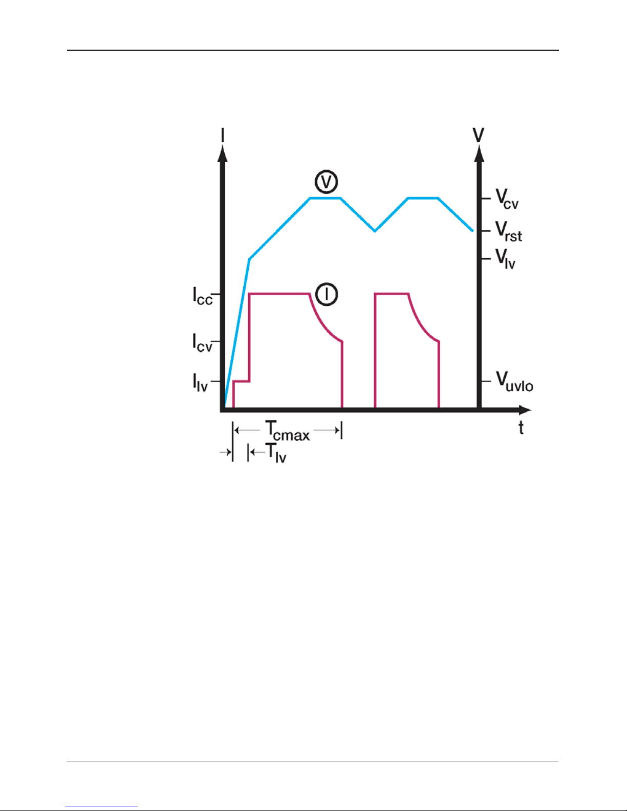
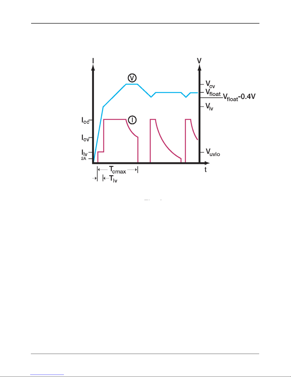
The Model 1620 charger provides three different charge profiles: IVa (Off Mode,
see Figure 1), I1VI2a (Equalize Mode, see Figure 2) and IV1V2(Float Mode, see
Figure 3).
For definitions of the variables mentioned in this section, refer to Table 1.
Curtis 1620 Manual page 2
Radiated Emissions: FCC Part 15, Class A EN55011, Class A
Conducted Emissions: FCC Part 15, Class A EN55011, Class A
EN50082-1-1997 — X
ESD: — EN61000-4-2:1995
Radiated Immunity: — EN61000-4-3:1995 +
A1:1998
Electrical fast transient: — EN61000-4-4:1995
Surge Immunity: — EN61000-4-5:1995
Conducted Immunity: — EN61000-4-6:1996
Power Frequency Magnetic Field: — EN61000-4-8:1993
Voltage dips and sags: — EN61000-4-11:1995
Harmonics: — EN61000-3-2:2000
Voltage fluctuations (flicker) — EN61000-3-3:1995
Safety — EN60335-1:1995
EN60335-2-29:1997
J2-1
J2-2
J2-3
100V max., 60mA max.
Curtis 1620 Manual
page 1
2.7.1 – End of Charge Mode
Figure 1. Charge profile for End of Charge Mode
Figure 1 defines the charge profile for the End of Charge Mode. As long as the
battery voltage (V) is above Undervoltage Lockout Level (Vuvlo), charging will
start after short delay of about 6 seconds. For battery voltage between Vuvlo and
Vlv, charge current will be limited to lower value (Ilv) in order to prevent gassing
damage to the batteries. Good batteries will quickly increase voltage above Vlv
and the 1620 will increase current to Constant Current value (Icc).
This is beginning of a bulk charge, which typically returns 80% of the charge. At
the end of bulk charging, battery voltage has reached Constant Voltage level (Vcv)
and the charger will maintain the voltage by reducing the current (I) gradually.
When the current drops to Icv, charging will stop, at which point the charger has
returned 105-110% of the Ampere-hours discharged.
If the battery is not used, its voltage will slowly drop due to self-discharging.
When battery voltage reaches Restart Voltage (Vrst), the 1620 will turn back on
and fully charge battery again.
Curtis 1620 Manual
page 3
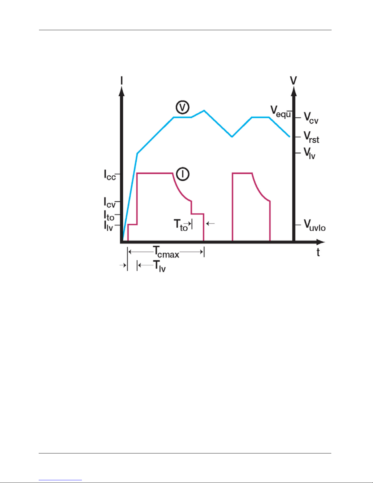
2.7.2- Equalize Mode after End of Charge Mode
Figure 2. Charge profile for Equalize Mode
Figure 2 defines the charge profile for the Equalize Mode. After going through
bulk charge and Constant Voltage modes, the charger will reduce its output cur-
rent to Top-Off Current (Ito) until one of the two possible outcomes occurs:
(1) Battery voltage rises to Equalize Voltage (Vequ) or
(2) Equalize Time-Out (Tto) is reached.
Once one of these two possibilities occur, charging will stop and the 1620 will set itself
to Off Mode; the charger remains in standby until restart voltage (Vrst) is reached.
Curtis 1620 Manual page 4
Curtis 1620 Manual
page 1
2.7.3 - Float Mode
Figure 3. Charge profile for Float Mode
Figure 3 defines the charge profile for the Float Mode. In this mode of operation,
batteries are maintained at full charge. In addition to maintaining full charge, the
charger can support a load current – as long as the combined load current and
battery charging requirements do not exceed the output current defined in the
Constant Current setpoint (Icc, default value of 20A in the Basic Mode).
In this mode of operation, the charger will go through bulk charge and Constant
Voltage modes as previously described. It then goes into standby until the battery
voltage drops 0.4V below the Float Voltage (Vfloat, default value of 26.8VDC in
Basic Mode) setpoint. The charger will then reactivate and maintain float voltage
as long as the current requirement is above 2A. If current drops to 2A, the charger
will again enter standby mode. The charger will continue this cycle of standby/
reactivation until power is removed or until the Model 1311 programmer is con-
nected.
Curtis 1620 Manual
page 5

2.8 Indication Lights
The charger features built in diagnostics. Refer to the table below to interpret the
flashing of the green and yellow indicator lights.
Curtis 1620 Manual page 6
Flash Pattern Mode Charge Status
Yellow on, Green on Standby Indicator 1 Charge done, ready to use.
Yellow on, Green blinks1Charging Charging normally.
Yellow and Green blink1together Standby Indicator 2 Charge cycle has not started,
refer to troubleshooting section.
Yellow and Green blink alternately Programming 1311 programmer connected to the unit.
Yellow blinks1, Green on Standby Indicator 3 End of Charge (Veoc) voltage reached.
Charge done, ready to use.(200s delay)
Yellow blinks1, Green off Error Charge cycle stopped,
refer to troubleshooting section.
Yellow blinks2once, Error Charge cycle stopped,
2 seconds off, repeats, Green off refer to troubleshooting section.
Yellow blinks2twice, Error Charge cycle stopped,
2 seconds off, repeats, Green off refer to troubleshooting section.
No indicators on Off/Error Charger is unplugged, otherwise
refer to troubleshooting section.
1– 0.5s on, 0.5s off
2– 0.5s on

Curtis 1620 Manual
page 1 Curtis 1620 Manual
page 7
INSTALLATION
3.1 Unit should be securely mounted to a flat surface.
3.2 The power cord to the IEC 320/C14 connector should be of the appropriate
gauge to carry a 15A current, for the cable’s length, to meet the requirements
of applicable electrical codes. The power cord must meet IEC requirements
with a minimum cross section of 1.5mm.
3.3 The wires between the charger output and the battery should be of the
appropriate gauge to carry a 20A current, for the cable’s length, to meet the
requirements of applicable electrical codes. An inline fuse (32V min. 30A
max.) is recommended to protect against accidental battery short circuit.
3.4 A minimum of 30mm clearance should be provided at each vented end of
the charger.
3.5 Charger should not be installed in locations which restrict airflow to the
unit.
3.6 The circuit supplying power to the charger should be rated at a minimum of
15A for a 120VAC circuit, or for 5A for a 230VAC circuit.
3
Questo manuale è adatto per i seguenti modelli
1
Indice
Altri manuali Curtis Caricabatterie per batterie


