Cutler-Hammer SV9000 Manuale utente

USER'S MANUAL
LONWORKS®
Option Board
SV9000
AF Drive
Subject to changes without notice

SV9000 LONWORKS
®
Option Board manual Page 1
_________________________________________________________________________________________
_________________________________________________________________________________________
Cutler
-
Hammer
INDEX
1. INTRODUCTION.................................................................................................................................................2
1.1 General...........................................................................................................................................................2
1.2 About this manual...........................................................................................................................................2
1.3 Safety Precautions .........................................................................................................................................2
2. SPECIFICATIONS ..............................................................................................................................................3
3. LONWORKS®.....................................................................................................................................................4
3.1 Overview.........................................................................................................................................................4
3.2 Physical media and wiring..............................................................................................................................4
3.3 Bus termination ..............................................................................................................................................5
3.4 Service button and LED..................................................................................................................................6
4. INSTALLATION ..................................................................................................................................................7
5. CONNECTIONS..................................................................................................................................................9
5.1 Board layout ...................................................................................................................................................9
5.2 I/O-control connections ................................................................................................................................10
6. COMMISSIONING ............................................................................................................................................11
7. SV9000 LONWORKS®INTERFACE................................................................................................................12
7.1 Network Variables ........................................................................................................................................12
7.1.1 Network Input variables in the SV9000 ................................................................................................12
7.1.2 Network Output variables from the SV9000.........................................................................................13
7.1.3 Network Configuration variables to the SV9000...................................................................................15
Echelon, LonTalk, LONWORKS, LONMARK, Neuron and 3120 are trademarks of Echelon Corporation
registered in the United States and other countries.
SV9000 LONWORKS
®
Option Board manual Page 2
_________________________________________________________________________________________
_________________________________________________________________________________________
Cutler
-
Hammer
1. INTRODUCTION
1.1 General
SV9000 drives can be connected to a LONWORKS®network using the SV9NCLCN option board kit. The
drive can then be controlled, monitored and programmed from the LONWORKS® network.
The LonWorks® option board can also extend the used I/O:
x
4 digital inputs (standard signals)
x
4 digital outputs (standard signals)
x
thermistor input (can be directly connected to the motor thermistors for overtemperature trip)
x
Encoder input
The interface board must be installed in the external option enclosure outside the drive.
1.2 About this manual
The purpose of this manual is to provide you with the information how to install and set up your SV9000
LONWORKS®Option Board for communication over a LONWORKS®network. For more specific
information on installation and operation of the SV9000 refer to the SV9000 Drive User’s Manual and
SV9000 Fieldbus Application User’s Manual.
This manual assumes that you are familiar with the SV9000 drive and are using the LONWORKS®Option
Board with a SV9000 drive using the application for fieldbus support. It is also assumed that you are
familiar with LONWORKS®and its installation procedures and tools.
1.3 Safety Precautions
Before starting the installation, carefully read all warnings and safety instructions in the SV9000 Drive
User’s Manual.
Internal components and circuit boards (except the isolated I/O terminals) are at utility
potential when the SV9000 is connected to the utility. This voltage is extremely dangerous and
may cause death or severe injury if you come in contact with it.
The control I/O terminals are isolated from the utility potential, but the I/Os (if jumper X9 is in
OFF-position) may have a dangerous voltage connected even if the power is off on SV9000.

SV9000 LONWORKS
®
Option Board manual Page 3
_________________________________________________________________________________________
_________________________________________________________________________________________
Cutler
-
Hammer
SPECIFICATIONS
Bus Interface Channel FTT-10A Free Topology transceiver
connections Transfer cable Twisted pair
I/O -control Digital input (4 pcs) 24 V (
r
15 %), Ri= 5 k
:
connections Digital output (4 pcs) Open collector output, 50 mA/48 V
thermistor input (1 pcs) Rtrip = 4.7 k
:
Encoder input (3 pcs) 24 V (
r
30 V): “0”
d
10 V, “1”
t
18 V, Ri= 3.3 k
:
5 V (
r
10 V): “0”
d
2 V, “1”
t
3 V, Ri= 330
:
Aux. voltage 24 V (
r
20%), max 50 mA
Safety Fulfills EN50178 standard
Table 1-1. Specifications
The control connections are isolated from the utility potential and the I/O ground is connected to the
frame of the device via a 1 M
:
resistor and a 4.7 nF capacitor*. The control I/O ground can also be
connected directly to the frame by changing the position of jumper X9 (GND ON/OFF) to the ON-
position. Digital inputs are isolated from the I/O ground.
* Default value (X9 is in the GND OFF- position)

SV9000 LONWORKS
®
Option Board manual Page 4
_________________________________________________________________________________________
_________________________________________________________________________________________
Cutler
-
Hammer
2. LonWorks®
2.1 Overview
Echelon Corporation has developed LonWorks® technology. LONWORKS®network is used for
applications in industry and building automation, controlling household electronics, medical
instrumentation and many others. The goal of the LONWORKS®network is to provide a common
vendor independent communication network for intelligent devices.
In a LONWORKS®network, no central control or master-slave architecture is needed. Nodes on a
network communicate with each other using the LonTalk®protocol. Interoperable nodes use
Standard Network Variable Types (SNVT) for communicating over the network. The definition of
an SNVT includes units, a range, and an increment. SV9000 LONWORKS®uses only Standard
Network Variable Types as data types.
All network variables are either input (data comes from the network to the device) or output (data
is sent to the network from the device) network variables. When network variables on different
nodes on the network have been bound together by an installation tool, passing of data is
automatic between the right nodes. Only the same type of network variables can be bound
together, so it is very important to have compatible interfaces.
2.2 Physical media and wiring
LONWORKS®networks can be implemented on many different physical media. SV9000 SV9NCLW
option board is equipped with an FTT-10A transceiver supporting the Free Topology transformer
coupled network, which allows the network wire to be connected as bus, star, loop or mixed.
Communication speed with this media is 78kBits/s. The FTT-10A transceiver is compatible with
Echelon’s LPT-10 Link Power Transceiver, and these transceivers can communicate with each
other on a single twisted pair cable.
termination termination
Figure 2-1 Doubly Terminated Bus Topology
termination
Figure 2-2 Singly Terminated Bus Topology

SV9000 LONWORKS
®
Option Board manual Page 5
_________________________________________________________________________________________
_________________________________________________________________________________________
Cutler
-
Hammer
termination
Figure 2-3 Star Topology
termination
Figure 2-4 Loop Topology
Up to 64 FTT-10 transceiver nodes are allowed per network segment, the individual segments can be
connected together by a router. See table 3-1 for recommended cable types and cable lengths for FTT-
10. Even though unshielded cable types are recommended to be used with this type of transceiver, it is
still highly recommended to use only shielded cables with drives. Attention should be paid to proper
grounding of the shield to ensure bus operation, grounding of the shield should be done on both ends of
the cable.
Cable type Max. doubly
terminated
bus length
Max. free
topology
wire length
Max. node-to-
node
distance
Belden 85102 (unshielded) 2700 m 500 m 500 m
Belden 8471 (unshielded) 2700 m 500 m 400 m
Level IV, 22AWG (unshielded) 1400 m 500 m 400 m
JY (St) Y 2x2x0.8mm (shielded) 900 m 500 m 320 m
Table 2-1 FTT-10 wiring
2.3 Bus termination
The FTT-10 network segment requires termination for proper data transmission performance. A total
termination impedance of approximately 52.3:is required.
In a free topology segment, only one termination is required and may be placed anywhere on the free
topology segment. In a doubly terminated bus topology, two terminations are required, one at each end
of the bus.
The SV9000 SV9NCLW option board is equipped with termination resistors, which can be selected by
jumper X6. If the jumper is in the ‘ST’ position single termination is selected and if it is in ‘DT’ double
termination is selected. If termination is not done at this node the jumper should be removed or
positioned so that it is connected to one pin only.

SV9000 LONWORKS
®
Option Board manual Page 6
_________________________________________________________________________________________
_________________________________________________________________________________________
Cutler
-
Hammer
2.4 Service button and LED
Every LONWORKS®device has a service button, which is needed during network installation. Pressing
the button causes the node to send its unique ID number to the network. Because the SV9000
LONWORKS®Option Board is located under drive’s cover in normal use, the service button operation can
be done by changing the value of a service button parameter from 0 to 1 or vice versa on the SV9000
operating panel. The location of the service button parameter depends on the used SV9000 application.
Each LONWORKS®device should also have a service LED on it. The LED shows the operating state of
the device by blinking. On SV9000 the operating state can be seen on the operating panel as actual
value 22. See table 3-2 for coding of the states.
Node State State Code Service LED
Applicationless and Unconfigured 3 On
Unconfigured 2 Flashing
Configured 4 Off
Table 2-1 Service LED states

SV9000 LONWORKS
®
Option Board manual Page 7
_________________________________________________________________________________________
_________________________________________________________________________________________
Cutler
-
Hammer
3. INSTALLATION
Before starting the installation, carefully read the safety instructions in the " SV9000 Drive User's
Manual" chapter “SAFETY”. Check that you have recieved all the LONWORKS® kit parts: Repeater board
on mounting board, power cable (black terminal), data cable (blue terminal) and LONWORKS®board in
the separate option enclosure.
Repeater board with mounting board can be installed in the existing option board place inside the drive
(see figure 4-1).
ARemove the control panel and the jumper X4 from the control board. Install the jumper that
you removed from terminal X4 of the control board, on terminal X9 of the Fieldbus board in
the ON or OFF position.
BConnect the power cable to terminal X5 of the control board and the data cable to terminal
X14. The power cable can also be connected to terminal X6 if the power cable from the
power board is connected to terminal X5.
CPut the data and power cables through the holes in the mounting board.
DInstall the mounting board on the standoffs by the larger holes and push it into the right
position in the slots on the standoffs . Check that the mounting board is stable and secure it
with a screw to the lower left standoff. If you have difficulties to place the board, slightly bend
regulator A4 and capacitor C59 of the control board.
EConnect the power cable to terminal X1 of the Repeater board and the data cable to
terminal X2.
FConnect the cable coming out of the option enclosure to terminal X3 of the repeater board.
Find the closest grounding terminal on the drive and strip the cable so that you can
ground the shield under the grounding terminal.
GAfter this install the control panel back in its place.
H If you use a 5 V encoder input, install the jumper in terminal X7 (see figure 5-1) of the
LONWORKS®board

SV9000 LONWORKS
®
Option Board manual Page 8
_________________________________________________________________________________________
_________________________________________________________________________________________
Cutler
-
Hammer
X2
X1 X3
X5
X14
Figure 3-1. Repeater board on mounting board installed on top of the control board
SV9000 LONWORKS
®
Option Board manual Page 9
_________________________________________________________________________________________
_________________________________________________________________________________________
Cutler
-
Hammer
4. CONNECTIONS
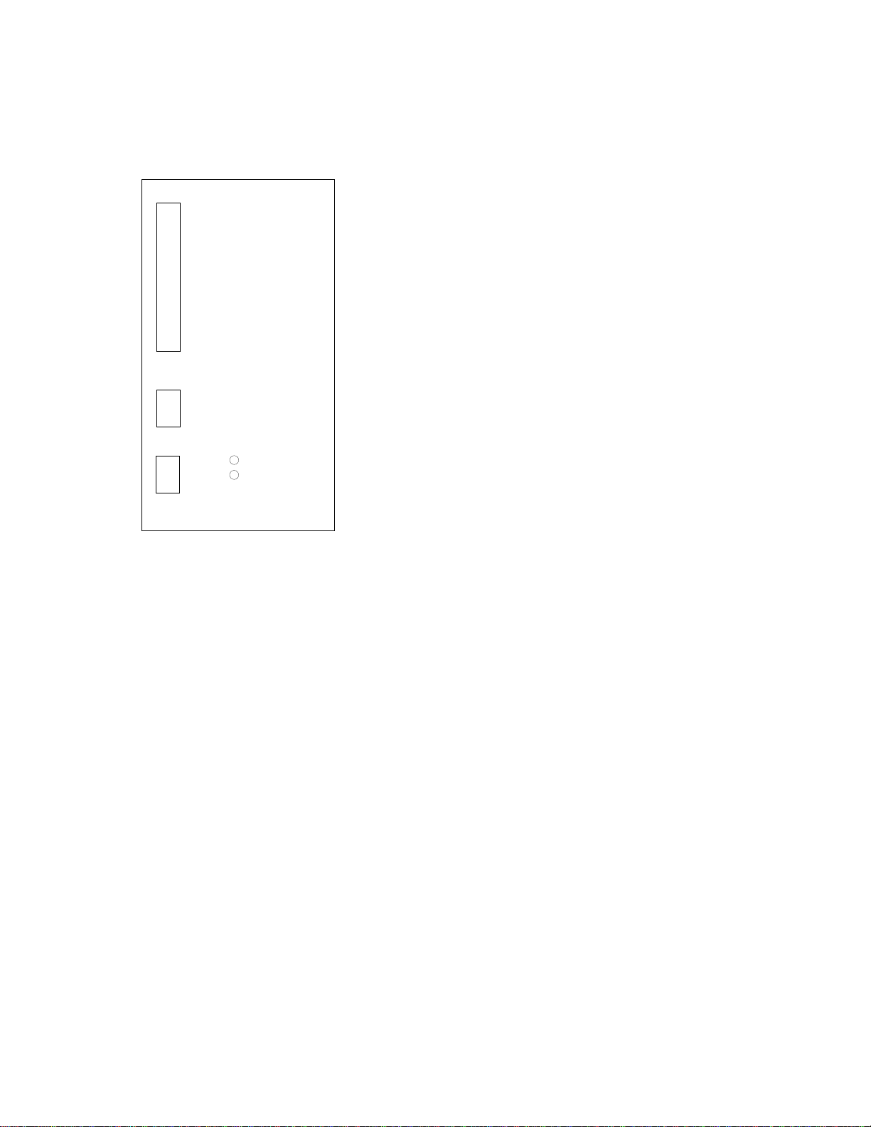
4.1 Board layout
Terminals:
X10 I/O - terminals
X11 thermistor input
X5 LONWORKS®network
Diagnostic LED:
power Supply Voltage, Green.
Power led is active if the interface board has supply voltage.
service Neuron’s service pin, Green.
See table 3-2. for operation of this led.
X10
X11
power
service
X5
Figure 4-1. LONWORKS®option board
Indice
Manuali Hardware di rete popolari di altre marche

Matrix Switch Corporation
Matrix Switch Corporation MSC-HD161DEL Manuale utente

B&B Electronics
B&B Electronics ZXT9-IO-222R2 Manuale utente

Yudor
Yudor YDS-16 Manuale utente

D-Link
D-Link ShareCenter DNS-320L Manuale utente

Samsung
Samsung ES1642dc Istruzioni per l’uso

Honeywell Home
Honeywell Home LTEM-PV Istruzioni per il montaggio


