
Cyclops Lighting PR-300W Manuale utente

USER MANUAL
PR-300W
300 watts Warm White LED Profile

Caution!................................................................................................................. 3
Introduction........................................................................................................... 3
Safety instructions ............................................................................................... 3
Overview................................................................................................................ 4
Installation............................................................................................................. 5
Read ‘Safety information’ before installing the xture. .................................................................. 5
Fastening the xture to a at surface............................................................................................... 5
Mounting the xture on a truss ......................................................................................................... 5
Securing with a safety cable.............................................................................................................. 6
DMX-512 connection/connection between xtures......................................................................... 6
Art-Net Connection............................................................................................................................. 7
Power connection............................................................................................................................... 7
Operation............................................................................................................... 8
Control Menu Map............................................................................................................................... 8
Control menu....................................................................................................................................... 9
Main Menu ........................................................................................................................................... 9
Addressing ........................................................................................................................................10
Universal DMX Control.....................................................................................................................10
RDM control.......................................................................................................................................10
Art-Net protocol ................................................................................................................................11
Rotary Knob function .......................................................................................................................11
Set dimmer curves............................................................................................................................12
Zoom ..................................................................................................................................................13
DMX Protocol...................................................................................................... 14
Fixture Cleaning ................................................................................................. 14
Fuse Replacement.............................................................................................. 14
Troubleshooting ................................................................................................. 14
The xture does not work, no light .................................................................................................14
Technical specications.................................................................................... 15
Table of contents

3V1.0
Caution!
Be careful with your operations. With a dangerous voltage you can suffer a dangerous electric
shock when touching the wires!
Avoid looking directly into the light source!
Wear protective glasses and other PPE (personal protective equipment) when working on or near
the xture.
For your own safety, please read this user manual carefully before you initial start-up.
Follow operating safety precautions and pay attention to warning signs methods and equipment
on the user manual.
Indoor use only! To prevent risk of re or shock, do not expose this product to rain or moisture. IP
20 rating.
The ambient temperature must always be between -5° C and +45° C.
Always make sure you are connecting this product to the proper voltage in accordance with the
specications in this manual or on the product’s specication label.Make sure it is grounded when
using it!
Unplug mains lead before opening the housing!
Make sure that the power cord is never crimped or damaged by sharp edges. Check the xture
and the powercord from time to time.
Make sure to replace the fuse with another of the same type and rating.
Warning! This symbol indicates a hot surface. Certain parts of the housing can become hot
during operation. After use, wait for a cool-down period of at least 10 minutes before handling or
transporting the device.
Every person involved with the installation, operation and maintenance of this device has to
- be qualied
- follow the instructions of this manual
- consider this manual to be part of the total product
- keep this manual for the entire service life of the product
- pass this manual on to every further owner or user of the product
- download the latest version of the user manual from the Internet
Introduction
Thank you for having chosen PR-300W. You will see you acquired a powerful and versatile device.
Unpack your item. Before you initial start-up, please make sure that there is no damage caused by
transportation. Should there be any, consult your dealer and do not use the device.
Safety instructions
This device has left our premises in absolutely perfect condition. In order to maintain this condition and
to ensure a safe operation, it is absolutely necessary for the user to follow the safety instructions and
warning notes written in this user manual. Always disconnect from the mains, when the device is not in
use or before cleaning it. Keep away children and amateurs from the device! There are no serviceable
parts inside the device. Maintenance and service operations are only to be carried out by authorized
dealers.

4V1.0
Overview

5V1.0
Installation
Read ‘Safety information’ before installing the xture.
The xture is designed for indoor use only and must be used in a dry location with adequate ventilation.
Ensure that none of the xture’s ventilation slots are blocked.
Fasten the xture to a secure structure or surface. Do not stand it on a surface or leave it where it can
be moved or fall over. If you install the xture in a location where it may cause injury or damage if it falls,
secure it as directed in this user manual using a securely anchored safety cable that will hold the xture if
the primary fastening method fails.
Fastening the xture to a at surface
The xture can be fastened to a hard, xed, at surface that is oriented at any angle. Ensure that the
surface and all fasteners used can support at least 10 times the weight of all xtures and equipment to
be installed on it.
Fasten the xture securely. Do not stand it on a surface or leave it where it can be moved or fall over.
If you install the xture in a location where it may cause injury or damage if it falls, secure it as directed
below with a securely anchored safety cable that will hold the xture if the primary fastening method fails.
Mounting the xture on a truss
The xture can be clamped to a truss or similar rigging structure in any orientation. When installing the
xture hanging vertically down, you can use an open-type clamp such as a G-clamp. When installing in
any other orientation, you must use a half-coupler clamp that completely encircles the truss chord.
To clamp the xture to a truss:
1. Check that the rigging structure can support at least 10 times the weight of all xtures and equipment
to be installed on it.
2. Block access under the work area.
3. Fold the legs of the mounting bracket together and bolt a rigging clamp securely to the mounting
bracket. The bolt used must be M10, grade 8.8 steel minimum. It must pass through both mounting
bracket legs and be fastened with a self-locking nut.
4. Working from a stable platform, hang the fixture with its clamp on the truss and fasten the clamp
securely.
5. Secure the xture with a safety cable as directed below.

6V1.0
Securing with a safety cable
Secure the xture with a safety cable (or other secondary attachment) that is approved for the weight of
the xture so that the safety cable will hold the xture if a primary attachment fails.
Loop the safety cable through the eyebolt in the back of the xture and around a secure anchoring point.
Do not loop the safety cable around the fixture’s mounting bracket only, as this will leave the fixture
unsecured if it separates from the bracket.
DMX-512 connection/connection between xtures
DMX/RDM
controller
Occupation of the XLR-connection:
1. Group
2. Signal (-)
3. Signal (+)
DMX OUT
1. Group
2. Signal (-)
3. Signal (+)
DMX IN
If you are using controllers with this occupation, you can connect the DMX-output of the controller directly
with the DMX-input of the rst xture in the DMX-chain. If you wish to connect DMX-controllers with other
XLR-outputs, you need to use adapter-cables.
Building a serial DMX-chain:
Connect the DMX-output of the rst xture in the DMX-chain with the DMX-input of the next xture.
Always connect one output with the input of the next xture until all xtures are connected.
DMX-512 connection with DMX terminator:
For installations where the DMX cable has to run a long distance or is in an electrically noisy
environment, such as in a discotheque, it is recommended to use a DMX terminator. This helps in
preventing corruption of the digital control signal by electrical noise. The DMX terminator is simply an
XLR plug with a 120 resistor connected between pins 2 and 3, which is then plugged into the output XLR
socket of the last xture in the chain.
Caution: At the last fixture, the DMX-cable has to be terminated with a terminator. Solder a 120 Ω
resistor between Signal (–) and Signal (+) into a 3-pin XLR-plug and plug it in the DMX-output of the last
xture.

7V1.0
Art-Net Connection
Connect the Ethernet inputs of all xtures with the Ethernet network.
Switch/Router PC/Controller
Art-Net Art-Net
Occupation of the RJ45-connection:
PR-300W installs two RJ45 connectors for DMX data transmission. Pin 1 is for data +, Pin 2 for data -,
Pin 7 & 8 for earthing.
12345678
Ground
-
+
NET IN
+
-
Ground
12345678
NET OUT
Power connection
Power Requirements
The PR-300W luminaire operates on 100 to 240 volts AC (+/- 10%, auto-ranging). The luminaire contains
an auto-ranging power supply.
Power linking between xtures:
The xture with powercon in and out socket. Connect the power out to the power in socket in the next
xture till all are connected.
Caution: maximum power linking - 6 units.
Connection with the mains:
Connect the device to the mains with the enclosed power supply cable.
The occupation of the connection cables as below:
Cable color Connection International
Brown Live L
Blue Neutral N
Yellow/green Earth(Ground)

8V1.0
Operation
The PR-300W can operate in three different modes. In each mode you can run the xture as a stand
alone fixture or in a master/slave confiugration. This next section will detail the differences in the
operating modes.
Control Menu Map
Default setting in bold.
MAIN MENU LEVEL 1 LEVEL 3 LEVEL 3 FUNCTION INSTRUCTION
DMX 001-512 DMX address setting
Network
DHCP DHCP(Dynamic Host Conguration
Protocol) mode
Manual
IP address xxx.xxx.xxx.xxx Fixtures' IP address (assigned via
DHCP, if active)
Net Mask
255.0.0 Net Mask for class A IP address
255.255.0.0 Net Mask for class B IP address
255.255.255.0 Net Mask for class C IP address
Mode
DMX 1/2/3CH DMX channel mode
ArtNet
Net 000-127 Set Art-Net net
SubNet 000-015 Set Art-Net subnet in Art-Net net
Universe 000-015 Set Art-Net universe in Art-Net
subnet
Channel 1/2/3CH Art-Net channel mode
Auto Program 001-008 Preset programs
Speed 001-009 Programs speed
Maunal Brightness 000-255 Dimmer 0-100%
Strobe 000-255 Strobe with speed increasing
Dimmer
Curve 0.3-3.0 Dimmer curves adjustment
Mode
Standard Dimmer mode, Standard
Stage Dimmer mode, Stage
TV Dimmer mode, TV
Architecture Dimmer mode, Architecture
Theatre Dimmer mode, Theatre
Custom
Fade in
(150 ms~2230 ms) Custom dimmer curve
Fade out
(150 ms~2230 ms)
Advance Authorization On/Off
Advanced settings/calibration(Only
qualied technicians should perform
this function. Inqure your local
dealer for password.)

9V1.0
Signal Priority DMX DMX/Art-Net signal priority setting
ArtNet
Signal Hold On/Off Run if signal cut
RDM On/Off RDM function on/off
Screen Timeout 30S Display shut off time
Never
Screen Brightness 10-100% Display brightness
Reset Yes/No System reset
Reverse Yes/No Display reverse 180 degree
Control menu
The information menu will appear after the xture is switched on. In this menu, the following status is
displayed:
Main Menu
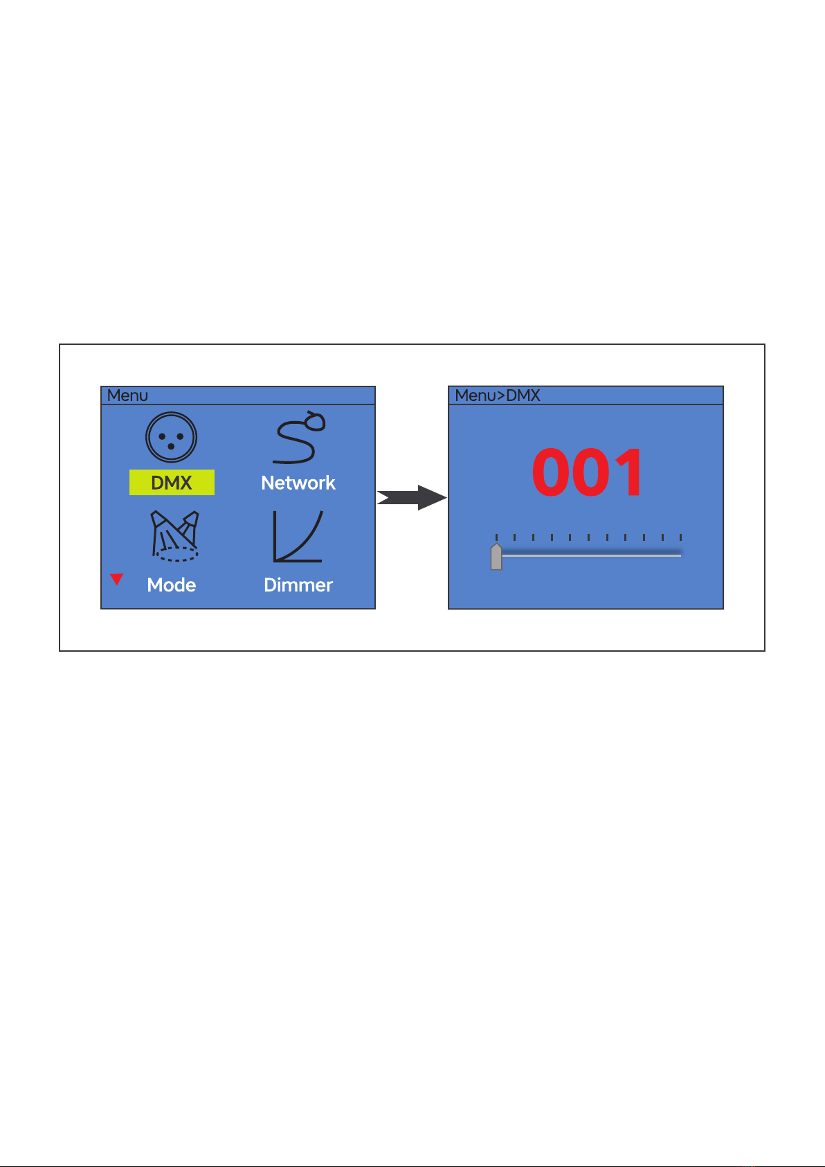
Press the MENU button to enter the Main Menu interface.
10 V1.0
Addressing
All xtures should be given a DMX starting address when using a DMX signal, so that the correct xture
responds to the correct control signals. This digital starting address is the channel number from which
the xture starts to listen to the digital control information sent out from the DMX controller. The allocation
of this starting address is achieved by setting the correct number on the display located on the base of
the device.
You can set the same starting address for all xtures or a group of xtures, or make different address for
each xture individually.
If you set the same address, all the units will start to listen to the same control signal from the same
channel number. In other words, changing the settings of one channel will affect all the fixtures
simultaneously.
If you set a different address, each unit will start to listen to the channel number you have set, based on
the quantity of control channels of the unit. That means changing the settings of one channel will affect
only the selected xture.
In the case of the PR-300W, which is 1/2/3 channels xture. If you set, for example, the address in the 1
channel mode to channel 2, the device will use the channel 2 for control.
Note: After switching on, the device will automatically detect whether DMX 512 data is received or not. If
there is data received at the DMX input, you will see the DMX indicator light in green.
Universal DMX Control
This function allows you to use a universal DMX-512 controller to control the dimmer and strobe. A DMX
controller allows you to create unique programs tailored to your individual needs.
RDM control
The PR-300W can communicate using RDM (Remote Device Management) in accordance with ESTA’s
American National Standard E1.20-2006: Entertainment Technology RDM Remote Device Management
Over DMX512 Networks.
RDM is a bi-directional communications protocol for use in DMX512 control systems, it is the open
standard for DMX512 device conguration and status monitoring.
Indice
Altri manuali Cyclops Lighting Attrezzatura per DJ

Cyclops Lighting
Cyclops Lighting FR-40W Manuale utente

Cyclops Lighting
Cyclops Lighting FR-40F Manuale utente

Cyclops Lighting
Cyclops Lighting PAR-150FZ Manuale utente

Cyclops Lighting
Cyclops Lighting PR-40C Manuale utente

Cyclops Lighting
Cyclops Lighting FR-300C Manuale utente

Cyclops Lighting
Cyclops Lighting PAR-350W Manuale utente

Cyclops Lighting
Cyclops Lighting PAR-150WZ Manuale utente

Cyclops Lighting
Cyclops Lighting PAR-150CZ Manuale utente

Cyclops Lighting
Cyclops Lighting PR-300C Manuale utente

Cyclops Lighting
Cyclops Lighting FR-50T Manuale utente


