
Daiwa D-17 Manuale utente

Installation & Manual
Central Heating Stove With Solid Fuel
Model D-17
Tested according to DIN EN 13240
For product efficiency and emission values, see the declaration of
conformity!
TR

2
TABLE OF CONTENTS
1. INTRODUCTION ...................................................................................................................................................3
2. GENERAL INFORMATION.....................................................................................................................................4
3. SAFETY .................................................................................................................................................................4
4. INSTALLATION ASSEMBLY AND CONNECTION ....................................................................................................5
4.1 SAFETY DISTANCES (MINIMUM DISTANCE)...................................................................................................5
4.2 STOVE INSTALLATION AND CONNECTION.....................................................................................................6
4.2.1 Expansion Tank.......................................................................................................................................6
4.2.2 Circulation Pump ....................................................................................................................................7
4.2.3 Mechanical Thermostat..........................................................................................................................7
4.2.4 Indicator Panel........................................................................................................................................8
4.2.5 Hot water for USE...................................................................................................................................9
4.2.6 Chimney Connection ..............................................................................................................................9
4.2.7 Radiator Installation Connection............................................................................................................9
5. STOVE WORK PRINCIPLES..................................................................................................................................10
5.1 SUITABLE FUEL.............................................................................................................................................10
5.2 FIRST USE OF STOVE ....................................................................................................................................10
5.3 COMBUSTION AND HEATING ......................................................................................................................11
5.3.1 Adding fuel............................................................................................................................................11
5.3.2 Use during transition period.................................................................................................................11
5.3.3 Ashtray Discharge.................................................................................................................................12
5.3.4 Emission Limit.......................................................................................................................................12
6. CLEANING AND MAINTENANCE.........................................................................................................................12
6.1 PROBLEM AND CAUSES ...............................................................................................................................13
7. GENERAL WARRANTY AND POLICIES.................................................................................................................14

3
1. INTRODUCTION
Central heating stoves provide a comfortable and easy-to-use interior aqueous
system. These heating units combine pleasure with a fireplace view. It is an
independent heating unit that provides heat dissipation of radiators, heat
distribution to the whole house and hot water through heat exchanger or boiler.
The stove body is made of steel.
The ashtray is placed at the bottom of the product and a fire chamber is available.
Water chamber is located on three sides (right, left and rear) of the combustion
and heating area.
Chimney output is placed on the upper plate of the product.
The product is highly efficient due to its physical structure.
It has an automatic ash discharge system.
There is an easy replaceable grid system.
The thermostat in the product ensures that the circulation pump prevents
automatically, thus avoids the continuous consumption of the electricity.
Circulation pump works quietly and the electricity consumption is up to a light
bulb.
Once the air flow is set, the system automatically starts getting fresh air through
the mechanical thermostat. Thus, fuel savings can be ensured by using the product
in the desired degree.
You have a solid fuel central heating stove with European Standards Quality
Certificate.
Please read the user manual, carefully. It includes information on product
functions and easy-to-use information.
Use of these information increases the product quality and extend its life. You can
properly protect the fuel and the environment.
Warranty of the product depends on the right use of installation and instructions
as described in the guide.
We recommend you to keep this guide in order to reach the information about the
correct use of the stove at the beginning of every winter.

4
2. GENERAL INFORMATION
National Standards, European Standards, local regulations, construction
regulations, fire protection and safety regulations must be observed.
During the installation, one must contact a person who is authorized for the
chimney. The authorized person shall check the shape of the chimney connection
of the product in the prescribed directions. In addition, the product installation
and installation connection must be made by an authorized person. Before
installing the stove, the lifting capacity of the installation ground should be
checked whether it is resistant for the stove. In case of insufficient load resistance
or low lifting capacity, suitable precautions must be taken (eg put a stove lifting
plate).
3. SAFETY
THE VENTILATION CONDITIONS WHERE THE PRODUCT WILL BE INSTALLED
AND THE PROTECTION AGAINST FREEZING MUST BE TAKEN INTO
CONSIDERATION.
All the required standard examinations are tested for the product. The predicted
parameters associated with combustion efficiency and exhaust gas emissions are
observed. The stove type described in this manual has been tested according to the
BA 1, DIN 1881 EN13240 standards, by an approved agency.
Combustion chamber cover should be opened only to load the fuel. To avoid
hazards, the combustion chamber must be closed. For the efficient operation of
the stove, there must be minimum of fresh air flow in the room where it is
installed.
CAUTION! The stove can operate in conjunction with the existing multiple
flue systems. This should not be an aspirator, ventilator etc.
The combustion of combustible materials causes heat energy to heat the stove
surfaces (doors, door handles, flame monitor cover, side walls, front wall). These
parts should not be touched without heat-protective gloves.
CAUTION! Since the stove top surface might be hot, please do not put
combustible materials on it.

5
Hazardous materials (plastic, flammable substances, etc.) may cause chimney fires.
In this case, immediately close all the parts of the stove and call the fire0 fighting.
CAUTION! Check the water level in the stoves and radiators before use.
*** The stove should not be used without water.***
4. INSTALLATION AND CONNECTION
The packaging of the stove protects the product from damage in the best possible
way. However, the stove or its accessories may still be damaged during transport.
Therefore, after removing the stove from the package, check whether it is complete
and undamaged. In case of any damage, notify your dealer.
4.1 SAFETY DISTANCES (MINIMUM DISTANCE)
While installing the stove, the fire regulations and chimney’s instructions must be
complied. For any related questions please ask the chimney installer. Minimum
distances to be observed in flammable or heat-sensitive materials (eg furniture,
wallpaper, wood panels) (see diagram below) are:
A25cm from rear wall

6
B15cm from lateral wall and
C 80cm from the radiation area (front side of the product)
Flammable materials and furniture should not be placed at a distance of 80 cm in
the radiation area (C) of the flame monitoring cover.
This distance can be reduced to 40 cm when the protection panel is placed
between the stove and the materials that are likely to burn.
Minimum distances for flammable materials and furniture are indicated on the
product label and must not be exceeded. If the floor where the stove needs to be
installed is flammable or heat-sensitive, you should place the product on the
ground protection plate (eg marble or glass base).
In this case the minimum dimensions of stove bottom plate (look at drawing)
should be:
D 50cm (front length)
E 30cm (lateral length from the inner edge of the fire chamber cover)
You can order the floor protection plate from seller when you require.
4.2 STOVE INSTALLATION AND CONNECTION
Product installation and assembly should be done according to the user manual
and by an authorized person. Since our central heating stove with solid fuel for a
flat is designed for interior and provide heat to the ambient, it should not be
installed in bathroom, balcony, cellar, woodshed, etc… The distance between stove
and chimney must be close.
Select an appropriate place for the product. The expansion tank, circulation
pump, mechanical thermostat, indicator panel and chimney connection must
be installed as shown in the installation diagram.
4.2.1 Expansion Tank
After the connection of the expansion tank to the suitable place (wall), it must be
securely connected to the 1”pipe(PVC-metal) and must be connected to 1” records
on the stove, to hot - cold return output and to ¾ connection records on the
expansion tank (see assembly diagram)
7
The expansion tank vapor output (water discharge) is used to expel the water
vapor caused by pressure from the stove. The water vapor expels by taking a line
from vapor output (water discharge) to the wet floor.
CAUTION! When filling, the installation has to be carried out from any point of the
installation other than the expansion tank and the other outlet on the side should
be closed with a blind plug, but the vapor output (water discharge) on the
expansion tank must not be closed.
While adding water to the expansion tank, please check the water level, fill the
water up to half of the expansion tank.
4.2.2 Circulation Pump
Circulation pump and bypass line should be installed to the input of the radiators
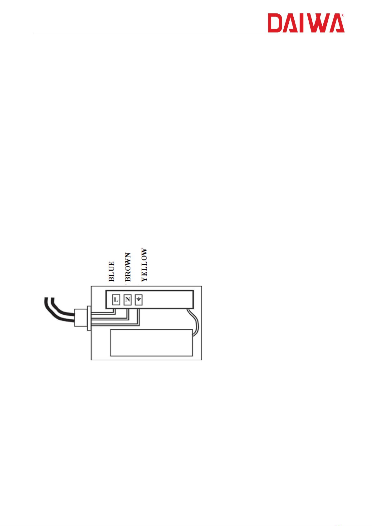
of the product as shown in (figure). The unshielded cable,located at the (rear)
part of the product, should be connected to the circulation pump as shown below.
4.2.3 Mechanical Thermostat
Your stove is equipped with a mechanical thermostat. Appropriate settings of the
mechanical thermostat is specified in the enclosed information page. In the stand-
by, you can save fuel and take advantage of optimal fuel energy if the
recommended settings are adhered to.
While Burning Stove: (Mechanical Thermostat Settings)

8
Fuel
Max. Fuel
Quantity
Mechanical thermostat
(Air passing through the
grate )
Glass Cleaning
Air - Condition
Wood
3 - 4 Parts
(Around. 3,5 - 4
kg)
First of all, burn 10 -15 min
at least at max.
Temperature (90Cº)
After set to the temperature
you need.
Open
Coal
Briquettes
(Around 3,5 - 4
kg)
First of all, burn 15-20 min
at least at max.
Temperature (90Cº)
After set the temperature
you need.
Open
The mechanical thermostat should be set to the highest degree (90ºC) when the
stove is burning.The chain connected to the mechanical thermostat and the vent
cover ensures wide opening of the vent cover. After about 15-20 min –the stove
becomes hot enough - you can set the Mechanical Thermostat to the required
temperature, it should not be under 40ºC; otherwise it will not cause rapid
combustion.
4.2.4 Indicator Panel
Electric Lamp: The electric lamp starts to last the moment we plug the stove into
the wall socket. If this lamp illuminates, it indicates that there is electricity. If the
lamp does not illuminate, check the power line.
Pump: the pump lamp indicates whether the circulation pump is activated.
Thermometer: the thermometer allows us to see the temperature of the water
inside the stove.
Boiler Thermostat: the boiler thermostat enables the circulation pump to operate
at a certain temperature. This temperature is between 35ºC and 45ºC.
CAUTION: Our electrical system operates at 220V / 50Hz. Our company is not
responsible for any voltage drop and/or rise of the electrical current.

9
4.2.5 Hot water for USE
There is a serpentine(flex pipe) system for hot water. In the serpentine system,
pressure reducers, valves or spiral hose must be used for hot-cold inlet-outlet. In
addition, if there is any problem in the product by connecting the serpentine
system heat safety valve (power failure, etc.), and the boiler water temperature
rises to 95 ºC, it opens the way of the heat exchanger to allow the cold water to
circulate in the boiler and helps to reduce the heat of the boiler water and prevent
it from going out again.
4.2.6 Chimney Connection
For stove connection steel sheet flue pipes of 2mm thickness must be used. Stove
pipe must be connected to stove chimney output and chimney firmly. This strong
and close connection is also compulsory for flue pipes. After connecting flue pipe to
the chimney, remaining gaps around chimney must be closed with sealing and
fireproof materials. When the distance between stove and chimney is long,
horizontal connection must be avoided. Chimney pipe must be installed according
to the direction of the chimney. When the distance is short at least 1meter length
flue pipe must be used and must be installed vertically.
The chimney to be used at the exhaust gas outlet can be multiple chimney
connection (See Chimney Assembly Diagram)
CAUTION: Do not burn the stove when the flue pipe is connected. First of all,
the radiator installation must be done ( Otherwise stove burned without
water can lead to stove deformations). Our company is not responsible for
damages caused by burning without water.
The chimney connection should be done according to DIN4705.
4.2.7 Radiator Installation Connection
Stove radiator plumbing connections should be installed by an expert or qualified
person to guarantee a technically correct operation. Our company is not
responsible for any mistakes that will occur while installing and assembling.
The radiator wiring connection of the stove should only be made with quality and
tried-and-tested safety equipment.
Plumbing main line pipes, for metal and plastic PVC Pipes should be at least 1’’. In a
heating system installed like this, the circulation ( hot water circulation ) will be
easy, comfortable and the temperature of radiators is felt earlier. The main line
pipes of the last few radiators can be ¾” metal and a plastic PVC pipe.

10
The main pipes in the heating system should be connected to the radiator
installation by using the connection parts as seen in the installation diagram
(records, valves, nipples).
CAUTION: Depending on the climatic conditions of the regions, certain
amounts of antifreeze must be added. Our company is not responsible for
any damages caused by not using antifreeze.
CAUTION: The plumbing pipes should not be routed as far as possible
through concrete floors and should be isolated if required. Otherwise, it
cannot get enough efficiency, heat loss may occur.
5. STOVE WORK PRINCIPLES
The stove should only be used by adults. Children should not be alone with the
stove. The stove should only be used in accordance with this manual.
5.1 SUITABLE FUEL
Stove is suitable for highly efficient fuels. Approved fuel for combustion is listed in
the attached information sheet.
CAUTION : Since wood is not a permanently combustible fuel, it is impossible
to heat overnight
CAUTION: Never use wallpaper, chipboard waste, plastic or treated wood
(paint, coating, etc.) for heating! Otherwise, the chimney and flue pipes may
be blocked.
Caution: Do not use flammable materials (thinner, paint, gasoline etc.)
5.2 FIRST USE OF STOVE
After the installation process of the product is completed, heating water
(installation water) will being added to the stove and radiators. The added water
could be observed from the water level indicator of the expansion tank. Check if
there are any leakages in the installation and radiators, in case of no leakage
connect the product plug to the electrical power.
Check the electrical power and observe the light and whether the inner shaft
rotates, by removing the yellow screw located in the middle part of the circulating
pump. If the shaft does not rotate, rotate it with the screwdriver, and put the
yellow screw in place.
Indice


