TABLE
OF
CONTENTS
1.0
Introduction
...........................................................................................1
2.
Equipment
needed
to
do
installation
..............................................1
3.0
Jumper
settings
....................................................................................1
3.1
Reserved
jumper
...........................................................................2
3.2
Primary/secondary
port
address
..............................................2
3.3
Initial
data
rate
control
jumper.
................................................2
3.4
Firmware/hardware
drive
select
jumper
.................................2
3.5
Floppy
precompensation
control...
............................................2
4.0
Installation
and
formatting
hard
disk
...........................................3
4.1
Floppy
drives
.................................................................................3
4.2
Hard
drives
.....................................................................................3
4.3
Formatting
the
drive
....................................................................3
DTC
Part
Number
09·00343·1
Revision
A
29·JAN·1987
This
installation
gUide
and
the
associated
software·
firmware
are
copyrighted
(c)
1983,
1984
DTC
..
1.0
INTRODUCTION
The
DTC
5280CRA
controller
is
designed
to
function
as
a
combination
hard
drive
and
floppy
drive
controller
in
"AT"
type
systems
that
do
not
have
the
floppy
drive
function
on
the
motherboard
or
on
another
board
in
the
system.
The
5280CRA
is
able
to
control
two
5.25"
or
3.5"
Winchester
or
removable
cartridge
hard
disks
and
two
floppy
disk
drives.
2.0
EQUIPMENT NEEDED TO DO INSTALLATION
The
following
equipment
is
needed
to
install
the
DTC
5280CRA
controller:
For
one
hard
disk
and
one
or
two
floppies
ea
20
pin
data
cable
ea
34
pin
cable
ea
34
pin
daisy
chain
calbe
For
two
hard
disks
and
one
or
two
floppies
2
ea
20
pin
data
cables
2
ea
34
pin
daisy
chain
cables
Software:
IBM
Advanced
Diagnostics
Program
diskette
or
a
similar
formatting
utility.
3.0
JUMPER SETTINGS
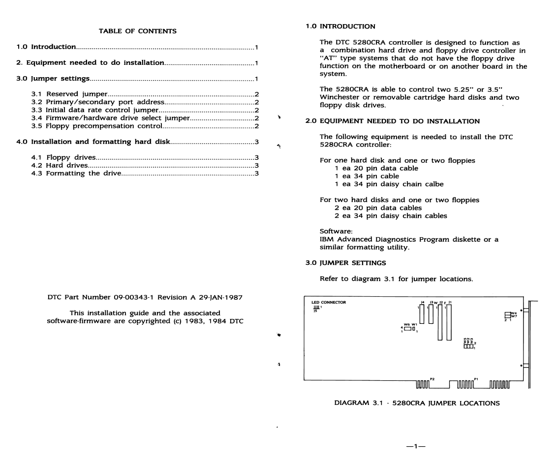
Refer
to
diagram
3.1
for
jumper
locations.
LED
CONNEcroR
lUl'
lS
DIAGRAM 3.1 .
5280CRA
JUMPER LOCATIONS
-1-