Datalogic PWR-240B Manuale utente

PWR-240B
INSTALLATION MANUAL
Reading Station Power Supply

Datalogic S.r.l.
Via S. Vitalino, 13
40012 Calderara di Reno (BO)
Italy
Tel. +39 051 3147011
Fax +39 051 3147205
©2020-2023 Datalogic S.p.A. and /or its affiliates
All rights reserved. Without limiting the rights under copyright, no part of this documentation may be
reproduced, stored in or introduced into a retrieval system, or transmitted in any form or by any means, or
for any purpose, without the express written permission of Datalogic S.p.A. and/or its affiliates.
Owners of Datalogic products are hereby granted a non-exclusive, revocable license to reproduce and
transmit this documentation for the purchaser's own internal business purposes. Purchaser shall not
remove or alter any proprietary notices, including copyright notices, contained in this documentation and
shall ensure that all notices appear on any reproductions of the documentation.
Electronic versions of this document may be downloaded from the Datalogic website (www.data-
logic.com). If you visit our website and would like to make comments or suggestions about this or other
Datalogic publications, please let us know via the "Contact" page.
Disclaimer
Datalogic has taken reasonable measures to provide information in this manual that is complete and accu-
rate, however, Datalogic shall not be liable for technical or editorial errors or omissions contained herein,
nor for incidental or consequential damages resulting from the use of this material. Datalogic reserves the
right to change any specification at any time without prior notice.
Trademarks
Datalogic and the Datalogic logo are registered trademarks of Datalogic S.p.A. in many countries, including
the U.S.A. and the E.U.
All other trademarks and brands are property of their respective owners.

INSTALLATION MANUAL
iii
TABLE OF CONTENTS
PREFACE ..................................................................................................................IV
About this Manual ........................................................................................................... iv
Manual Conventions ........................................................................................................................... iv
Technical Support ........................................................................................................... iv
Support Through the Website ............................................................................................................ iv
Reseller Technical Support ................................................................................................................ iv
Safety Regulations ........................................................................................................... v
Electrical Safety ...................................................................................................................................v
Product Data Label .............................................................................................................................. v
CE Compliance ..................................................................................................................................... v
General View .................................................................................................................. vi
CHAPTER 1.
OPERATING FEATURES .........................................................................1
Description ...................................................................................................................... 1
Output Protection ............................................................................................................. 1
Light Overload .....................................................................................................................................1
CHAPTER 2.
PRE-INSTALLATION CHECKLIST ...........................................................3
System Wiring: DC Output ................................................................................................ 3
System Wiring: AC Input .................................................................................................. 4
System Wiring: Test ......................................................................................................... 4
CHAPTER 3.
MECHANICAL INSTALLATION................................................................5
Cabinet Mounting ............................................................................................................. 5
CHAPTER 4.
LOW VOLTAGE ELECTRICAL CONNECTIONS...........................................6
DC Low Voltage Cable Insertion ........................................................................................ 6
Cable Entry Plate .................................................................................................................................6
AS-I Cable Insertion ............................................................................................................................7
DC Voltage Terminal Block ............................................................................................... 7
DC OK Monitoring ................................................................................................................................8
DC Direct Output ..................................................................................................................................8
Laser Barcode Scanners ................................................................................................... 8
Supply Capacity When Wiring Directly to AS-I Compatible Scanners ..............................................8
AS-I Wiring Topologies .......................................................................................................................9
Installing Accessory Industrial Ethernet Switch ............................................................... 10
Route the Ethernet Cables through the Cable Entry Plate grommets to the devices. .......... 11
CHAPTER 5.
AC LINE VOLTAGE ELECTRICAL CONNECTIONS ................................... 12
AC Line Input Voltage ..................................................................................................... 12
12 Vdc Power Block Installation (Optional) ...................................................................... 14
CHAPTER 6.
TECHNICAL FEATURES ....................................................................... 16
APPENDIX A.
ELECTRICAL DIAGRAMS ................................................................... 17
PWR-240B Electrical Diagram ........................................................................................ 17

iv
PWR-240B
PREFACE
ABOUT THIS MANUAL
This Instruction Manual is provided for users seeking advanced technical information,
including installation, connections, maintenance and specifications.
Manual Conventions
The following conventions are used in this document:
The symbols listed below are used in this manual to notify the reader of key issues or
procedures that must be observed:
TECHNICAL SUPPORT
Support Through the Website
Datalogic provides several services as well as technical support through its website. Log
on to (www.datalogic.com).
For quick access, from the home page click on the search icon , and type in the name of
the product you’re looking for. This allows you access to download Data Sheets, Manu-
als, Software & Utilities, and Drawings.
Hover over the Support & Service menu for access to Services and Technical Support.
Reseller Technical Support
An excellent source for technical assistance and information is an authorized Datalogic
reseller. A reseller is acquainted with specific types of businesses, application software,
and computer systems and can provide individualized assistance.
NOTE: Contains important information necessary for proper installation
and use of the device.
CAUTION; This symbol advises you of actions that could damage equipment
or property.
HIGH VOLTAGE: This symbol alerts the user they are about to perform an
action involving, either a dangerous level of voltage, or to warn against an
action that could result in damage to devices or electrical shock. Opera-
tions having this symbol must be performed by qualified personnel only.

SAFETY REGULATIONS
INSTALLATION MANUAL
v
SAFETY REGULATIONS
Electrical Safety
This product conforms to the applicable requirements contained in the following Euro-
pean Standards:
• EN 61439-1
• EN 60204-1
• EN 60950-1 +A11 +A1 +A12 +A2
•EN62368-1
Product Data Label
The Product data label is located on the outside door panel.
Figure 1 – Product Data Label
CE Compliance
CE marking states the compliance of the product with essential requirements listed in
the applicable European directive. Since the directives and applicable standards are
subject to continuous updates, and since Datalogic promptly adopts these updates,
therefore the EU declaration of conformity is a living document. The EU declaration of
conformity is available for competent authorities and customers through Datalogic
commercial reference contacts. Since April 20th, 2016 the main European directives
applicable to Datalogic products require inclusion of an adequate analysis and assess-
ment of the risk(s). This evaluation was carried out in relation to the applicable points of
the standards listed in the Declaration of Conformity. Datalogic products are mainly
designed for integration purposes into more complex systems. For this reason, it is
under the responsibility of the system integrator to do a new risk assessment regarding
the final installation.
Warning
This is a Class A product. In a domestic environment this product may cause radio inter-
ference in which case the user may be required to take adequate measures.

PREFACE
vi
PWR-240B
GENERAL VIEW
Figure 2 - PWR-240B General View
1 Key Lock 6 Cooling Fan
2 Product Data Label 7 AC Line Input Terminal Block
3 AC Input Cable Compression Connector 8 Thermal-magnetic Circuit Breaker
4 Cable Entry Plate with Grommets 9 “DC OK” Terminal Block
5 Monophase Switching Power Supply 10 24 Vdc Terminal Block

INSTALLATION MANUAL
1
CHAPTER 1
OPERATING FEATURES
DESCRIPTION
The PWR-240B is an electrical cabinet housing a 24 Vdc power supply which is used to
power up a varying number of reading devices (depending on the product), along with
their relative accessory devices. See Chapter 4 for details.
As shown in the Electrical Diagram in Appendix A, the AC Input Line passes through a
protective thermo-magnetic circuit breaker and connects to the monophase switching
power supply.
The 24 Vdc output power is connected to the output terminal blocks through a direct
connection block. The direct connection block is protected by the internal power supply
features.
Two output power supply status monitoring signals (DC-OK) are provided to connect to
an optional digital alarm. If for some reason the output voltage is reduced by less than
90% of nominal) these lines open.
OUTPUT PROTECTION
This power supply is specifically designed to power Datalogic devices and implements
output protection according to the type of overload behavior.
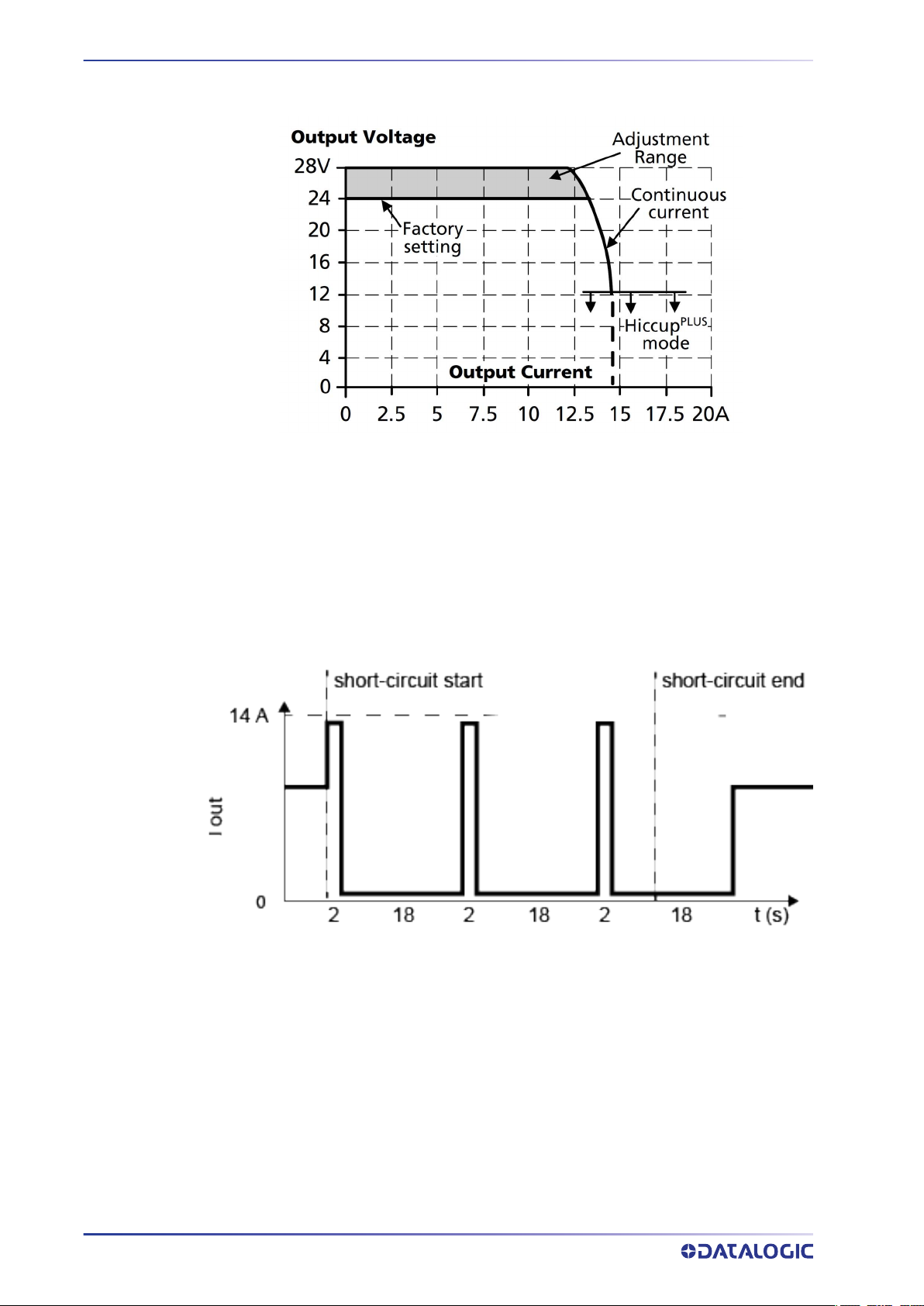
Light Overload
Light Overload is defined as application of a load that results in a reduction of the out-
put voltage that remains above 13V. In this case the power supply can deliver up to 14
amperes continuously, see Figure 3 Overload Behavior. Datalogic devices by their nature
OPERATING FEATURES
2
PWR-240B
cannot cause overload conditions since they are equipped with intrinsic power monitor-
ing systems. The AIR CLEANING SYSTEM fans also have this function.
Figure 3 - Overload Behavior
Heavy Overload (including short-circuit)
Heavy Overload is defined as application of a load which causes a reduction in voltage
below 13V. This causes the power supply to enter HICCUP operation where power is
supplied for 2 seconds and then shuts off for 18 seconds. This procedure is repeated
until the short-circuit or overload is resolved, see Figure 4 Short-Circuit Protection HIC-
CUP Mode. For this condition, the maximum length of the power cables between the
power supply and the powered devices guarantees the behavior of a short-circuit down-
stream of this cable.
Figure 4 – Short-Circuit Protection HICCUP Mode

INSTALLATION MANUAL
3
CHAPTER 2
PRE-INSTALLATION CHECKLIST
This chapter can be used as a checklist to verify all the steps necessary to complete
installation of the PWR power supply.
1. Read all information in this manual before installation, paying particular attention
to all Caution and Warning notes.
2. Mount the PWR to the Station frame using the brackets and bolts provided in the
package. See "Cabinet Mounting" on page 5.
SYSTEM WIRING: DC OUTPUT
3. Connect your devices to the PWR according to your application.
Barcode Scanners
Correctly connect the AS-I cabling to the PWR using the AS-I cable wiring instruc-
tions for backbone and branch wiring. See "Laser Barcode Scanners" on page 8 and
your scanner manual for details.
All cables must pass through the cable entry plate using the correct AS-I cable
grommets as described in "Cable Entry Plate" on page 6 and "AS-I Cable Insertion"
on page 7.
HIGH VOLTAGE: Opening the cabinet requires a key that should be used by a
person adequately advised or supervised by an electrically skilled person
to enable him or her to perceive risks and avoid hazards which electricity
can create. Internal components guarantee an IP20 degree of protection
against direct contact.

PRE-INSTALLATION CHECKLIST
4
PWR-240B
SYSTEM WIRING: AC INPUT
4. To comply with EN 60950-1:2007 par.1.7.2.2, par. 2.7.1, par 2.7.4, par. 3.4.6, and to
protect the AC input connection to the device; a disconnecting device with built in
overcurrent and earth protection shall be installed external to the equipment
according to local regulations.
According to EN 60950-1:2007 par. 3.2.3; the AC input cable must have a maxi-
mum diameter of 14mm and the conduit a max diameter of 16mm.
5. With AC line voltage OFF, wire the AC Line to the AC Line Input Terminal Block see
"AC Line Input Voltage" on page 12.
SYSTEM WIRING: TEST
6. Apply the AC line voltage from the building installation or the DWS-SWITCH and
check that the PWR powers up correctly. The green DC-OK light should be on
steady and the overload light (red) should off.
7. Close and lock the PWR enclosure and check that it does not open (lock functions
correctly).
The PWR-240B installation is now complete.
Indice
Altri manuali Datalogic Alimentazione elettrica


