Via monte Nero, 40/B – 21049 TRADATE (VA) ITALY
P
one: +39 (0)331841070 Fax:+39 (0)331841950 - e-m
ail:
[email protected] -
www.datexel.it
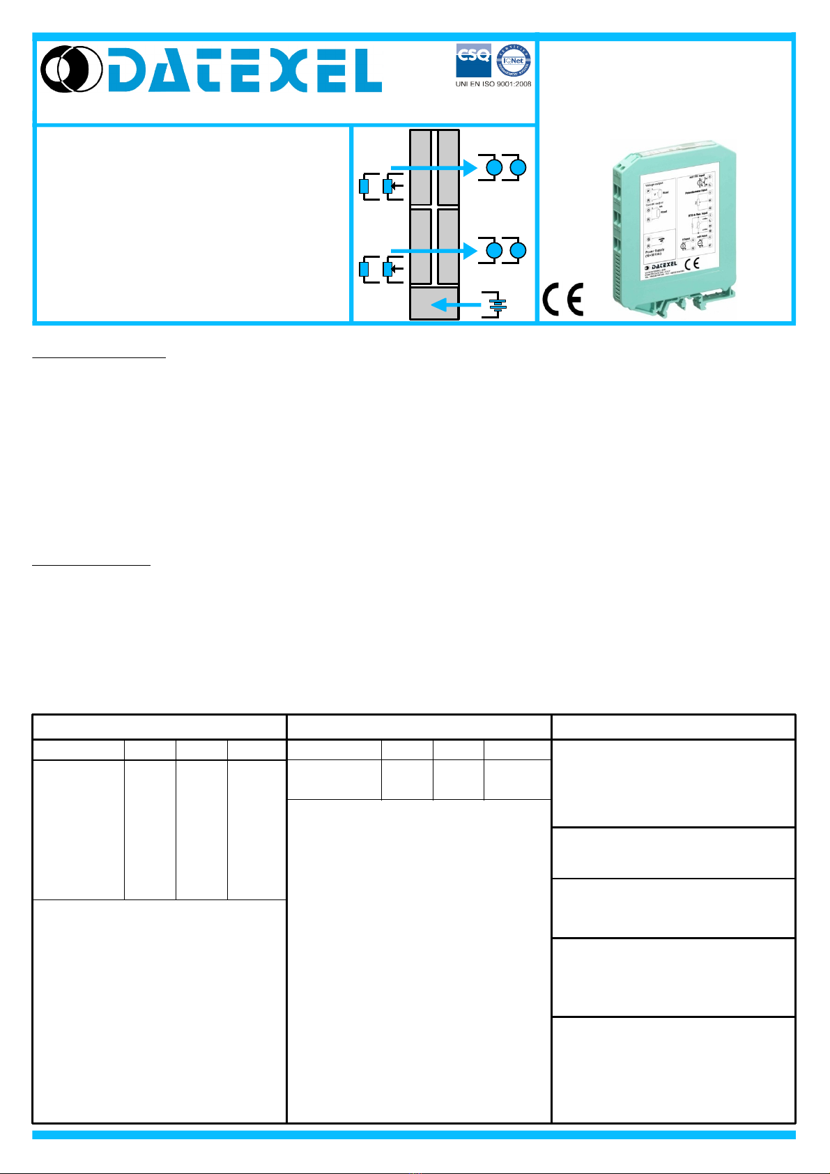
DAT 4532 C
DAT 4532 C
Isolated, double channel
converter for PTC/NTC/Pot
configurable b Dip-Switch or PC
FEATURES
- Configurable input for PTC, NTC and Pot.
- Configurable output in current or voltage
- Double channel in the same enclosure
- Configurable b dip-switch or PC
- High accurac
- On-field reconfigurable
- Galvanic isolation among the wa s
- EMC compliant – CE mark
- Suitable for DIN rail mounting in compliance
with EN-50022 and EN-50035
GENERAL DESCRIPTION
T e isolated double c annel converter DAT 4532 C is able to measure and linearise t e standard PTC and NTC sensors and potentiometers. In function
of programming, t e measured values are converted in a current or voltage signal. T e device guarantees ig accuracy and performances stability bot
versus time and temperature.
T e double c annel allows t e ig density mounting w ere is necessary to reduce t e encumbrances.
T e programming is made by t e dip-switc located in t e window on t e side of t e enclosure. By means of dip-switc es it is possible to select t e input
type and range and t e output type wit out recalibrate t e device.
Moreover, by Personal Computer t e user can program all of t e device's parameters for is own necessity; t e configuration by PC allows to program
t e two c annels wit two independent settings.
Moreover it is available t e option of alarm for signal interruption (burn-out) t at allows to set t e output value as ig or low out of scale .
T e 1500 Vac galvanic isolation on all ways (inputs, outputs and power supply) eliminates t e effects of all ground loops eventually existing and allows
t e use of t e converter in eavy environmental conditions found in industrial applications.
T e DAT 4532 C is in compliance wit t e Directive 2004/108/EC on t e Electromagnetic Compatibility.
It is oused in a plastic enclosure of 12.5 mm t ickness suitable for DIN rail mounting in compliance wit EN-50022 and EN-50035 standards.
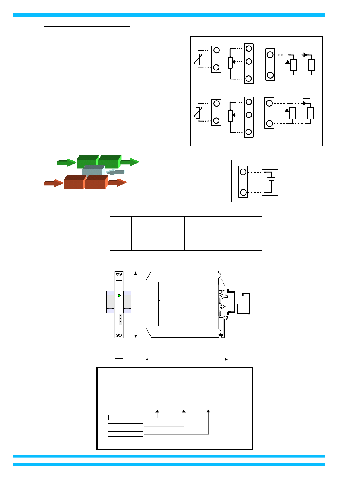
USER INSTRUCTIONS
T e converter must be powered by a direct voltage applied to t e terminals Q and R.
T e c annel A measures t e value from t e sensor connected to t e terminals I, L and G and transmits t e output measure on t e terminals N and M.
T e c annel B measures t e value from t e sensor connected to t e terminals E, F and H and transmits t e output measure on t e terminals P and O.
T e input and output connections must be made as s own in t e section "Connections".
It is possible to configure t e converter on field by dip-switc or Personal Computer as s own in t e section “ Programming ". T e configuration by
dip-switc es can be made also if t e device is powered (note: after t e configuration t e device takes some seconds to provide t e rig t output measure ).
TECHNICAL SPECIFICATIONS (T pical at 25 °C and in nominal conditions)
Sensor excitation current
PTC, NTC 500 uA
Linearit (1)
PTC, NTC ± 0.1 % f.s.
Thermal drift (1)
Full scale ± 0.01% / °C
TEMPERATURE AND HUMIDITY
Operative temperature -20°C .. +60°C
Storage temperature -40°C.. +85°C
Humidity (not condensed) 0 .. 90 %
Output t pe Min Max Min Span
HOUSING
Material Self-extinguis ing plastic
Mounting DIN rail in compliance
wit EN-50022 and
EN-50035
Weig t about 90 g.
Output calibration
Current ± 7 uA
Voltage ± 5 mV
Power supply voltage 18 .. 30 Vdc
Reverse polarity protection 60 Vdc max
EMC ( for industrial environments )
Immunity EN 61000-6-2
Emission EN 61000-6-4
Current consumption
Current output 55 mA max.
Voltage output 25 mA max.
Burn-out values
Max. output value 22 mA or 10.6 V
Min. output value 0 mA or -0.6 V
Current 0 mA 20 mA 4 mA
Voltage 0 V 10 V 1 V
(1)referred to t e input Span (difference between max. and min.)
Response time (10÷ 90%) about 500 ms
Output load Resistance - Rload
Current output < 500 Ω
Voltage output > 10 KΩ
S ort circuit current 26 mA max.
ISOLATION
Among all ways 1500 Vac,
50 Hz, 1 min
POWER SUPPLY
INPUT (2 channels) OUTPUT(2 channels)
Input Calibration (1)
PTC, NTC t e ig er of ±0.1% and ±0.2°C
Potentiometer ± 0.05 % f.s.
Input t pe Min Max Min.Span
PTC
KTY81-210 -55°C 150°C 50°C
KTY81-220 -55°C 150°C 50°C
KTY84-130 -40°C 300°C 50°C
KTY84-150 -40°C 300°C 50°C
Pot. (Rnom.< 50KΩ) 0 %100 % 10 %
NTC
Coster 10K -10°C 100°C 50°C
Coster 1K -30°C 40°C 25°C
NTC
PTC Pot
VmA
VmA
DC SUPPLY
INPUT A OUTPUT A
+
-
INPUT B OUTPUT B
NTC
PTC Pot