DeLuxe Stitcher G8 Manuale utente
Before using this Stitcher Head, all operators must study this manual and follow the
safety warnings and instructions. Keep these instructions with the G8 Stitcher Head
for future reference. If you have any questions, contact your local DeLuxe Stitcher
Company Graphic Arts Representative or Distributor.
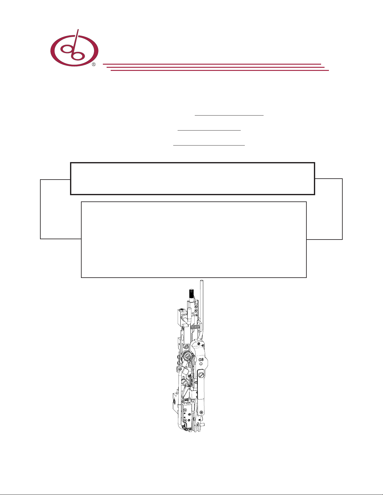
G8 Stitcher Head
OPERATION AND MAINTENANCE MANUAL
Wire Sizes: 23-28 Ga. Round, 20x24 and 21x25 Flat
Crown Size: 1/2” (13.5 mm)
Capacity: 2 sheets to 5/16” (8 mm) Standard
2 sheets to 5/32” (4 mm) Loop
Head Serial Number :
Date Purchased :
Where Installed:
(make/model of machine)
solving your wire stitching needs for 125 years...
DELUXE
STITCHER
COMPANY INC.
®

2

3

WARNING!
G8 Stitcher Head
Machine operators and others in the work area should always wear
safety glasses to prevent serious eye injury from
fasteners and flying debris when loading, operating,
or unloading this machine.
Do not operate this stitcher head without all stitcher machine
guards in place. Do not modify the guards in any way.
Always disconnect the power supply before removing
any guards for servicing.
Never operate the machine with wire feeding through
the head unless there is stock above the clinchers,
otherwise serious damage may result.
Always turn power off when making adjustments. Always
disconnect the power cord before any disassembly work.
4
EYEWEAR
REQUIRED

6
Safety Warning .................................................................................5
Introduction ........................................................................................................7
Part Number Definition....................................................................................7
Specifications.....................................................................................................9
Installation ......................................................................................................11
Pre-Inspection................................................................................11
Inspection ......................................................................................11
Assembly Parts .............................................................................12
Mounting .................................................................................... 13-14
Operation .......................................................................................................15
Wire Threading .......................................................................... 15-16
Wire Straightening ..................................................................... 17-18
Adjustments and Settings .......................................................... 19-24
Maintenance......................................................................................................25
Lubrication ................................................................................. 25-26
Cleaning ........................................................................................27
How to Order Spare Parts .............................................................28
Troubleshooting................................................................................................29
Formed Staple Chart .................................................................. 30-31
Appendices ......................................................................................................32
Exploded Drawings with Part Number/Description/
Cross Reference/Qty. ................................................................. 32-50
Optional Equipment........................................................................51-52
Parts Index......................................................................................................53-55
Warranty........ .....................................................................................................56
Registration Card.......................................................................................... 57-58
Common Replacement Parts.......................................................................58
Table of Contents

7
The part number for each Stitcher Head can be used to define the stitcher head itself, in most
cases. The Head’s model type, mounting style, nominal wire size and crown size can all be
determined from the part number.
G8 P HD 24 A 1/2
1/2 = Crown size in inches
A = Mount and Wire Guide Spring Type
24 = Wire Size
HD = Head
P = Original Equipment Manufacturer
G8 = Model type
Part Number Definition
Typical Style Uses:
G8BHD ............................................................. No. 2 and M2 Wire Stitchers
G8MHD .......................................................... No. 17 and M17 Wire Stitchers
G8HD .................................................................Automatic Saddle-Stitchers,
................................................................ Gang-Stitchers, Multibinders and Others
Examples of Replacement Heads for OEM Users*:
AM Graphics / Harris / Heidelberg / Sheridan 455, 562, 690............ G8HD24A
AM Graphics / Harris / Heidelberg / Sheridan 705 ............................ G8HD24A
C.P. Bourg ............................................................................................... G8HD24D
Christensen .............................................................................................. G8HD24A
Horizon SP, SPF ...................................................................................... G8HD24D
Macey Multibinder ................................................................................ G8HD24B
McCain .................................................................................................... G8HD24A
Rosback ................................................................................................... G8HD24B
Boewe 4601 .............................................................................................. G8BOHD241/2
McCain / OmegaBinder.......................................................................... G8HD23A
Harris 855 ................................................................................................ G8HD24-HARRIS
McCain / Sheridan / Harris / Bielomatik, ECH Will \ et.al................ G8HDC24A
Heidelberg ST100, ST270, ST300, ST350............................................. G8HEHD241/2
JMZ&A (Parker) .................................................................................... G8PKHD241/2
Watkiss .................................................................................................... G8WAHD241/2
* These are just a few examples of the replacement heads available for these OEM’s.
Introduction

8
Some Head Style Examples
Figure 1 - Style Comparisons
A9086A A9086A
A9086A 9193A
9193A

9
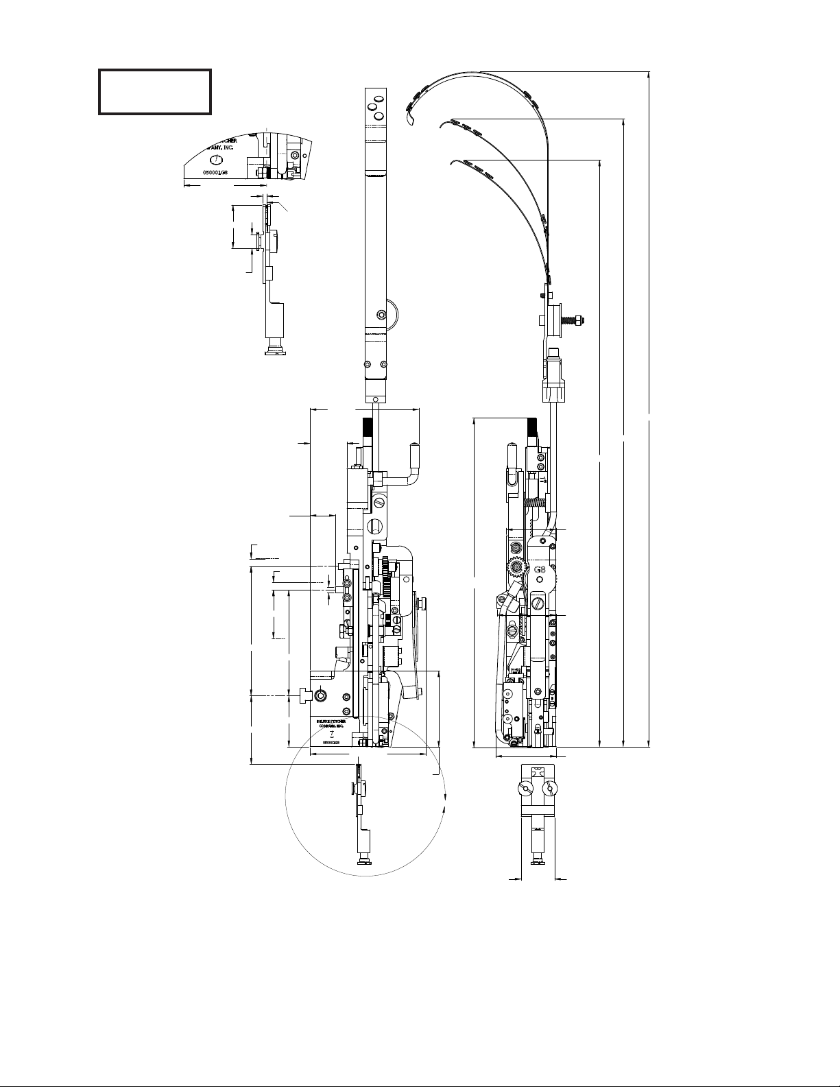
Specifications
Weight
Shipping Weight ..............13 lbs (5.9 kg)
Box Size ...................21 x 10 x 6
Physical Dimensions
Height ...................13-9/16” (345 mm)
Width ...................2-3/4” (70 mm)
Stitching Capacity ..................Two Sheets to 5/16” (8 mm)
...................Two Sheets to 13/64” (5 mm) Loop
(Stitching capacities are highly dependent on wire and paper type, tensile strength and machine capacity.)
Wire Types ...................23 through 28 round or
...................20x24,20x25 and 21x25 flat
...................(24 gauge round standard)
...................25 gauge only for Loop
Crown Sizes ...................1/2” (13mm)
...................13/64” (5mm) Loop
Minimum Head Centers
...................2-3/64” (52mm) at two sheets to
...................1/16” (1.5mm) material thickness
...................loop = 56mm at two sheets to 2mm
Stitches Per Hour ...................20,000 or 12,000 with Loop Head
Replacement for: ...................Interlake/Acme/Champion/
...................Magnatek/M2000 heads,
...................26/26D Model Heads, or Hohner
...................52/8, 55/7, 43/6 and 48/5 Heads
...................and others
Make sure all guards are in place before
operating the stitcher head
WARNING
!
10
Dimensions
27 5/8 [702]
25 11/16 [653]
21 1/32 [611]
13 9/16 [345]
MAX.
2 3/64 [52]
2 3/4" [70]2
1/4" [57]
2 7/16 [62]
1 3/8 [34.9]
2 13/16 [71.5]
4 23/64 [110.7]
5 21/64 [135.3]
2 3/32 [53.3]
5/16 [8]
5/16 [8]
4 1/2 [114]
1 1/32 [26]
1 1/2 [38.5]
4 25/32 [121.4]
3 9/64 [80]
THICKNESS
ADJUSTMENT
THICKNESS
ADJUSTMENT
DRIVE STROKE
A
2.256 [57.30]
5/32 [3.9]
1 3/16 [30.3]
3/8 [9.5]
DETAIL A
SCALE 1.5 : 1
CENTER OF
STITCH
2 [50.8] .248 [6.3]
Figure 1

11
Installation
As you carefully unpack the head, check to make sure all components were delivered and are in
good working order. Refer to Figure 2 in this manual for reference to the following pieces:
•G8Manual
•2.0mmHexKeyWrench(G20374)
•2.5mmHexKeyWrench(G20361)
•3.0mmHexKeyWrench(G20360)
•5.0mmHexKeyWrench(G20362)
•7.0mmOpenEndWrench(G20364)
•CompleteWireGuideSpringPlateAssembly(G20278AA)
•AdjustmentKnobAssembly(G20228A)
•Short(G20279A)orLong(G20286A)WireGuideSpringAssembly
•ClincherPlateAssembly-Thick(9086A)
•Round(CA9083A)orFlat(9083C)ThickClincherPoints
•ClampBlock(9002)andClampBlockEccentric(G20124)orRearClampPin(G20366)
and Rear Mounting Bolt (G20367 or G20341)
•EitherClincherPlateBinderNut(2091),Bolt(9088)andThickClincherSlide(CA9093A)
or Clincher Plate Binder Nut (2091), Bolt (9088), Adjustable Clincher Slide (9084B),
Clincher Slide Adjusting Screw (9087) and Clincher Slide Adjusting Lock Screw
(UA4808.7).
•StitchSamples
* Note: the accessories included with the G8 will vary with the style of Head purchased
Carefully inspect the condition of the shipping container before unpacking your G8 Stitcher Head.
If the container is broken or damaged and there is evidence that the stitcher head may be damaged,
immediately notify the carrier who delivered the head and the DeLuxe Stitcher Graphic Arts
Representative from whom the G8 Stitcher Head was purchased.
Pre-Inspection
Inspection
Altri manuali per G8
2
Indice


