
Detex EAX-300 Manuale utente

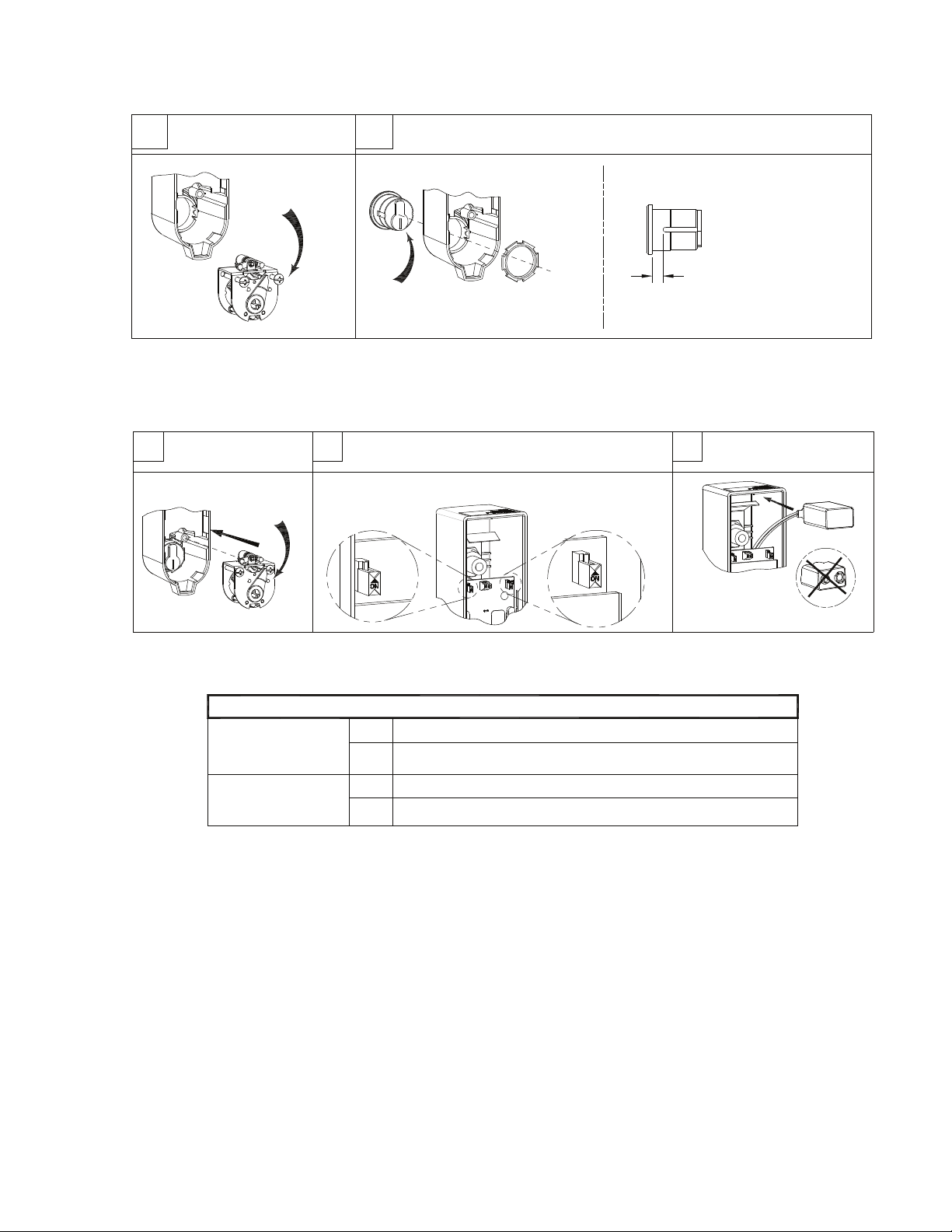
Set OKC cam
as shown
3 4
DP
(OFF)
Set selector switch functions (See Table A)
Re-install
cam assembly
CORRECT
WRONG
Connect 9-volt battery
and install as shown
5
(Default settings shown)
Collar required if distance
is greater than 5/16".
Optional collar can be ordered
from Detex (p/n: ECL-1595)
If 7-pin cylinder is used -
OBSERVE
Table A: Selector Switch Functions
STATUS
INDICATOR
(SWITCH B)
OFF* No indication that device is armed or disarmed.
ON
DP
(SWITCH A)
OFF*
Door chime mode
ON
Door prop mode
( *Default settings; **Will shorten battery life)
ARMED - red LED blinks approximately every 6 seconds.**
DISARMED - green LED blinks approximately every 6 seconds.**
STATUS
INDICATOR
(OFF)
A
AR
B
DP
NOTE: For "Key Stop", See Step 9
1
Install mortise cylinder with cylinder nut provided
Cam orientation as shown
with key removed
2
Mortise cylinder
Unfasten
(2) screws
STEPS 1-5: PREP DEVICE
Remove cam assembly
from cover
104889 Page 2

Install backplate with (2)
#1/4-20 or #14 screws
STEP 6: For all models except SK
DOOR PREP & BACKPLATE / MAGNET MOUNTING
Install magnet, backplate and cover
STEP 6: For SK models
BACKPLATE MOUNTING
Skip to Step 8 to continue non SK installation
NOTE: Remove locator and backplate prior to drilling mounting holes
Backplate
Drill #7 for #1/4-20
machine screws
Drill 7/32" or 3/16" for
#14 sheetmetal screws
Magnet
Drill #43 for #4-40
machine screws
Drill #44 for
#4 sheetmetal
screws
Backplate
Drill #7 for #1/4-20
machine screws
Drill 7/32" or 3/16" for #14 sheetmetal screws
Mark/drill backplate and magnet holes
on door and frame/mullion
Install magnet with (2)
#4-40 or #4 screws
Install backplate with (2)
#1/4-20 or #14 screws
FRAME/MULLION
DOOR
LHR installation shown
for reference only
104889 Page 3

1-1/2
Flex walls outward to remove guard
& board
1"
Drill 7/8 dia
(1) place
Recommended hole size
Common
Terminal
P/N: PP-5107
Closed Mag
Switch 1
Switch 2
Mag
Diagram shown typical for two door magnetic switches:
MS-1039S & MS-1059S wire in series.
MS-2049 (Red wire not used)
Weatherized not available for SK installations
Closed contact when door is closed
NOTES:
1. If wire runs longer than
10 feet, must use twisted pair
2. 1/16" slotted jeweler
screwdriver required.
3. If internal contact is used
DO NOT cut jumper (JP1)
Disconnect power &
cut (JP1) jumper
(see note 3 below)
STEP 7: Multi-door & SK function wiring connection
(if required)
(Recommended installation)
7a 7b 7c
7d Screw wires to (P1) terminal block
(18ga Max wire dia)
Reassembly:
Fitting or nut NOT included
Common
Closed
104889 Page 4

CORRECT
"ON" position
(Key can be removed)
"OFF" position
(Key cannot be removed)
.050" Hex Wrench
(NOT PROVIDED)
Rotate key to this
position before reinstalling
cam assembly
Mortise cam orientation
as shown
Key stop
installed
WRONG
Back View
Front View
KEY STOP POSITIONS
STEP 9:
KEY STOP INSTALLATION (Key stop included in hardware kit)
Top surface of Key Stop should
NOT protrude beyond highest
point on plastic cam
Install key stop
P/N: 102688
Cam orientation
for Key Stop option
Key and cams
shown in "OFF"
position
Key and cams
shown in 90°
stop "ON"
position
STEP 8: INSTALL DEVICE
Install device onto backplate
Turn key CW
to lock cover
Hook at bottom, then tilt
cover over backplate
ON
OFF
ON
OFF
ON
OFF
ON
OFF
ON
OFF
104889 Page 5

OPERATIONS
SPECIAL NOTES and DEFINITIONS:
1. The door needs to be closed to test the unit.
2. When operating the ON/OFF switch, there is a slight delay.
3. The key is inserted and removed only in the vertical position (home position).
4. Key function: counter clockwise (CCW) = Armed; clockwise (CW) = Disarmed
5. The door prop function is selectable by setting SWITCH A to the OFF position.
For door chime function, set SWITCH A to the ON position
MAGNET HANDING PROCEDURE: Magnet handing is where the device determines if the left,
right or an external reed switch will be used to indicate if the door is opened or closed. When the
battery is initially installed, the device simultaneously flashes the LEDs and chirps the siren a total
of five times. This indicates that the device is in the magnet handing process:
Step 1: If re-handing is necessary, remove the unit from the door, momentarily short the
REHANDING (orTest) jumper contacts. The device simultaneously flashes the LEDs and
chirps the siren a total of five times.
Step 2: Turn the key CW to the 'OFF' position.
Step 3: Install the device on the door.
Step 4: With the door open, turn the key CCW to the 'ON' position. The red LED blinks twice.
Step 5: Close the door and bring the external magnet into position with the external door switch.
The siren chirps and the LED flashes on the selected side of the device (red LED flashes for
the left side or external; green LED flashes for right side).
The device will now operate normally, and the selected reed switch side is stored in memory so
changing the battery does not require re-handing.
DOOR PROP OPERATIONS: The door prop function is selected by setting SWITCH A to the 'OFF'
position. To arm the system, close the door and turn the key CCW to the 'ON'
position. The red LED will flash twice indicating that the device is now armed. If the door is opened,
the device will begin a timing countdown according to the selected amount of time (15 seconds default).
If the Status Indicator (switch B) is 'ON', the red LED will blink every second during the countdown. If the door is not closed
before the door prop time runs out, the alarm sounds and the red LED flashes. Closing the door will silence the alarm and
rearm the unit. To change the door prop timing, see the section Changing Door Prop Timing.
DOOR CHIME OPERATIONS:
The door chime function is selected by setting SWITCH A to the 'ON' position.
To arm the system, close the door and turn the key CCW to the 'ON' position. The red LED will flash twice indicating
that the device is now armed. If the door is opened, the device sounds a series of siren chirps lasting
five seconds. No other action is taken until the door is closed and the unit rearms.
DISARMING: To turn off the alarm or disarm the system, turn the key CW to the 2 o'clock position.
TROUBLESHOOTING: If the unit does not arm, the magnet may need to be re-aligned or shimmed closer to
the EAX-300. If the unit fails to operate correctly, restart the device by removing the battery for approximately
five seconds.
LOW BATTERY ALERT: Simultaneous siren chirps and red LED flashes occur at 45 second intervals when
battery reaches approximately 7 volts. The LV Opt jumper must be in place to use this feature (default).
STATUS INDICATOR: With the Status indicator (SWITCH B) 'ON': red LED flashes every six seconds
when armed; green LED flashes every six seconds when disarmed.
"ON"
position
"OFF"
position
"ON"
position
Key orientation
without Key Stop
installed
Key orientation
with Key Stop
installed
"OFF"
position
ON
OFF
ON
OFF
ON
OFF
ON
OFF
REHANDING
(orTest) jumper
contacts.
LV Opt jumper
behind cover
(under SWITCH A)
104889 Page 6


PROBLEM
Device is not powering up.
Device not arming.
Chirp every 45 seconds
External magnet not working.
No connector for external magnet.
DOOR PROP
PROBLEM
After arming and door is opened, the
device chirps 4 times then shuts off.
DOOR CHIME
PROBLEM
After arming and door is opened, the
device blinks red.
TROUBLESHOOTING
PROBABLE CAUSE
1) Battery not properly installed.
1) Magnet not aligned correctly.
2) Battery is dead.
3) Cylinder had wrong cam installed.
4) Cylinder microswitch lever broken.
5) Cylinder installed incorrectly.
Low battery
Device is not set for external magnet.
Weatherized device.
PROBABLE CAUSE
The device is setup as Door Chime.
PROBABLE CAUSE
The device is setup as Door Prop
ACTION
1) Remove battery and firmly reinstall.
1) Use magnet locator to install magnet.
See magnet handing.
2) Replace battery.
3) Requires standard Yale cam.
4) Microswitch needs to be replaced.
Remove PCB and return to Detex Repair.
5) Check cylinder installation. Make sure key
is turned counter-clockwise all the way to ON.
Install new battery.
Cut JP1 jumper. With battery connected,
short "Test mode" pins, listen for 5 chirps.
See RE-HANDING section.
Weatherized device can not be used with
external contact.
ACTION
Reset device, slide Switch A to the OFF
position.
ACTION
Reset device, slide Switch A to the O
N
position.
104889 Page 8
Questo manuale è adatto per i seguenti modelli
2
Indice


