MAKING THE ELECTRICAL CONNECTIONS
WARNING: THIS WATER HEATER MUST BE EARTHED.
The electrical installation must be in accordance with the current BS.7671 (IEE Wiring Regulations)
and “Part P” of the Building Regulations and/or local regulations
Wiring to the mains (Check the unit rating to see which applies)
•A 40 amp 240V supply is required for the 9.5kW unit
•A 45 amp 240V supply is required for the 10.8kW unit
•A 50 amp 240V supply is required for the 12.0kW unit
9.5kW IL095 Wiring Conditions:
If the cable run is less than 10 metres and is surface run, 6mm² cable can be used.
A means for disconnection in all poles must be incorporated in the fixed wiring in accordance with
the wiring rules.
The isolating switch should be rated at: 40 amps or greater for the 9.5kW unit.
Wire the unit using a suitable Fuse/MCB: 40 amps Fuse/MCB for the 9.5kW unit.
12.0kW and 10.8kW IL095 Wiring Conditions:
This unit has been designed to accept 10mm² supply cable. Therefore, this is the size of cable that
should be used between the isolator switch and the unit, even if you decide to use 16mm² between
the fuse box and isolating switch. 10mm² supply cable is recommended for the 12.0kW, and for long
cable runs (greater than 10 metres) also for the 10.8kW unit.
The isolating switch should be rated at: 45 amps for the 10.8kW unit / 50 amps forthe 12.0kW unit.
Wire the unit using 10mm² cable and a suitable Fuse/MCB:
45 amps Fuse/MCB for the 10.8kW unit / 50 amps Fuse/MCB for the 12.0kW unit.
If the unit is fitted in a bathroom:
9.5kW and 10.8kW IL095: A standard 45 amp cord operated isolatorswitch is recommended.
12.0kW IL095: A pull cord isolator switch is not available for this model. A double pole 50 amp
isolator switchis required. This must be mounted out of reach ofthe shower cubicle or bath.
Connecting the unit to the mains
•Strip back the insulation on the LIVE (brown or red) and NEUTRAL (Blue or black) mains wires
about 8mm. Strip backany insulation on the EARTH (green/yellow or green) about 20mm.
•Feed the cable through the side or rear entry grommets, as appropriate.
If the side entry is used, this will stop water getting into the unit.
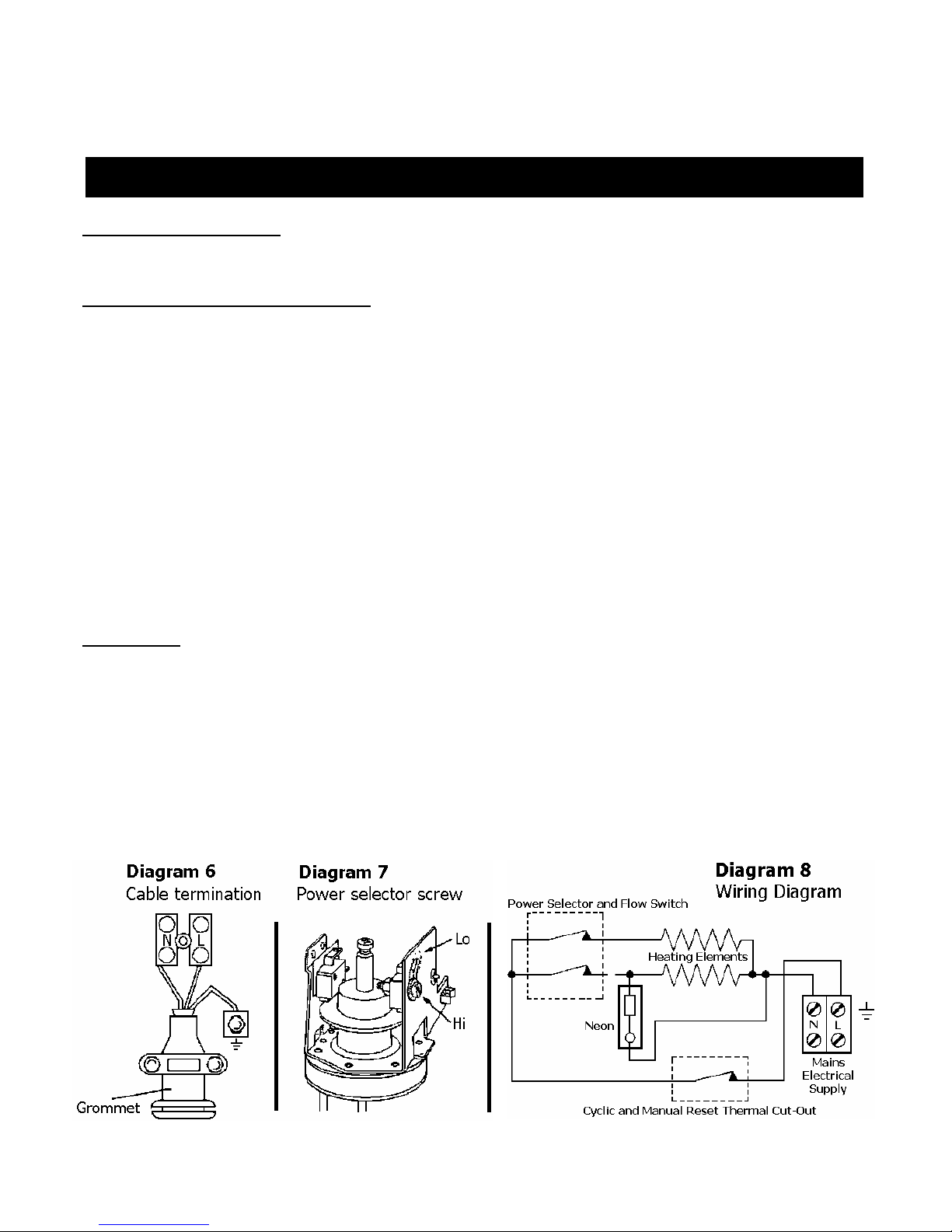
•Connect the cables to the terminal block and earth stud (diagram 6).
•Make sure that the live and neutral terminal block screws are tightened securely (1Nm minimum)
•Make sure that the earth wire is wrapped around its terminal stud and into the saddle washer.
The nut should be tightened securely (2 Nm minimum).
WARNING: FAILURE TO COMPLY WITH THESE INSTRUCTIONS COULD RESULT IN
FAILURE OF THE TERMINAL BLOCK
•Check that the Power Selector Screw) on theflow switch is set to “HI” (diagram 7).


 Guida alla risoluzione dei problemi")