DIRICKX AXIS DESIGN SYSTEM Nota di rilascio
F
AXIS®DESIGN
SYSTEM
WITH AXIS®AND AXOR®POSTS
Technical Handbook

CONTENTS
1 PAGES 3 TO 5Description - Delivery
6
PAGES 17 TO 19
Maintenance - Repairs
2 PAGES 6 TO 7Ground constraints
7
PAGES 20 TO 23
After-Sales service
PAGE 3
Setting AXIS®Design or AXOR®posts to be sea-
led in the ground or a low wall
1-2
PAGE 3
Recommendations for handling and storage
1-1
PAGE 8
Preparation - Civil engineering
3-1
PAGES 8 TO 11
Installation
3-2
PAGE 3
Description
1-2-1
PAGE 3
Components delivered according to order
1-2-2
PAGE 12
Ground mounting
4-1-1
PAGE 12
Mounting on a low wall
4-1-2
PAGES 17 TO 18
Setting the AXIS®Design or AXOR®repair post for concreting
6-2-1
PAGE 19
Setting the AXIS®Design repair post welded on a plate
6-2-2
PAGE 4
Setting AXIS®Design or AXOR®posts on base
plates fixed in the ground or on a low wall
1-3
PAGE 4
Description
1-3-1
PAGE 4
Components delivered according to order
1-3-2
PAGE 5
Setting AXIS®Design posts on wall brackets
1-4
PAGE 5
Description
1-4-1
PAGE 5
Components delivered according to order
1-4-2
3
PAGES 8 TO 11
Setting for concreting
AXIS®Design or AXOR®posts
in the ground or on a low wall
PAGE 12
Preparation - Civil engineering
4-1
PAGES 13 TO 14
Installation
4-2
4
PAGES 12 TO 14
Installation on base plates
AXIS
®
Design or AXOR
®
posts
at ground level or on a low wall
PAGE 15
Preparation - Civil engineering
5-1
PAGES 15 TO 16
Installation
5-2
PAGE 17
Maintenance
6-1
PAGES 17 TO 19
Repairs
6-2
PAGE 23
Claims
7-1
PAGE 23
Identification
7-2
PAGE 23
Guarantee
7-3
5
PAGES 15 TO 16
Installation using a bracket
AXIS®Design posts
on a wall
3
Issue 01 - 05 2003
1
Description
Delivery
1-1 Recommendations for handling and storage
1-2
Setting AXIS®Design or AXOR®posts to be concreted in the ground or a low wall
- Keep the packing on the palette before use in order to avoid any damage to the product and any aes-
thetic damage (to the coatings).
- At least 2 people are needed for setting the fence.
Tensioning
tools
Intermediate Post
for concreting
First Post
for concreting
Corner Post
for concreting
48
68
70
100
AXIS
Panel
®AXIS Post
for concreting
®AXOR Post
for concreting
®
POST DIMENSIONS
1-2-1 DESCRIPTION
- AXIS®Design or AXOR® Post(s) to be sealed (see pages 20 and 22) delivered on palette.
- AXIS®DR, D, PR, P or S Panels (see pages 22 and 23) delivered on palette.
- Packet(s) of tensioning tools delivered in a cardboard box.
1-2-2 COMPONENTS DELIVERED ACCORDING TO ORDER
Issue 01 - 05 2003
4
Ø 13
135
145
Ø 13
Tensioning
tools
Intermediate Post
on base plate
First Post
on base plate
Corner Post
on base plate
AXIS
Panel
®
AXIS Panel
on base plate
®AXOR Panel
on base plate
®
DIMENSIONS OF POSTS ON PLATES
85
100
135
145
85
100
1
Description
Delivery
1-3 Setting AXIS®Design or AXOR®posts on base plates fixed in the ground or on a low wall
1-3-1 DESCRIPTION
- AXIS®Design or AXOR®Post(s) on bases plates (see pages 20 and 22) delivered on palette.
- AXIS®DR, D, PR, P or S Panel(s) (see pages 22 and 23) delivered on palette.
- Packet(s) of tensioning tools delivered in a cardboard box.
1-3-2 COMPONENTS DELIVERED ACCORDING TO ORDER
Ø 14
Ø 13
Intermediate Post
on a bracket
First Post
on a bracket
Corner Post
on a bracket
Standard
Bracket
Facade
Bracket
E
E
Tensioning
tools
AXIS
Panel
®
5
Issue 01 - 05 2003
1
Description
Delivery
1-4
Setting AXIS®Design posts on wall brackets
1-4-1 DESCRIPTION
- AXIS®Design bracket Post(s) (see page 21) delivered on palette.
- AXIS®DR, D, PR, P or S Panel(s) (see pages 22 and 23) delivered on palette.
- Packet(s) of tensioning tools delivered in a cardboard box.
1-4-2 COMPONENTS DELIVERED ACCORDING TO ORDER
STANDARD BRACKET FACADE BRACKET
E : Distance between different brac-
kets according to the nominal
height of the fence (see page 21)
Issue 01 - 05 2003
6
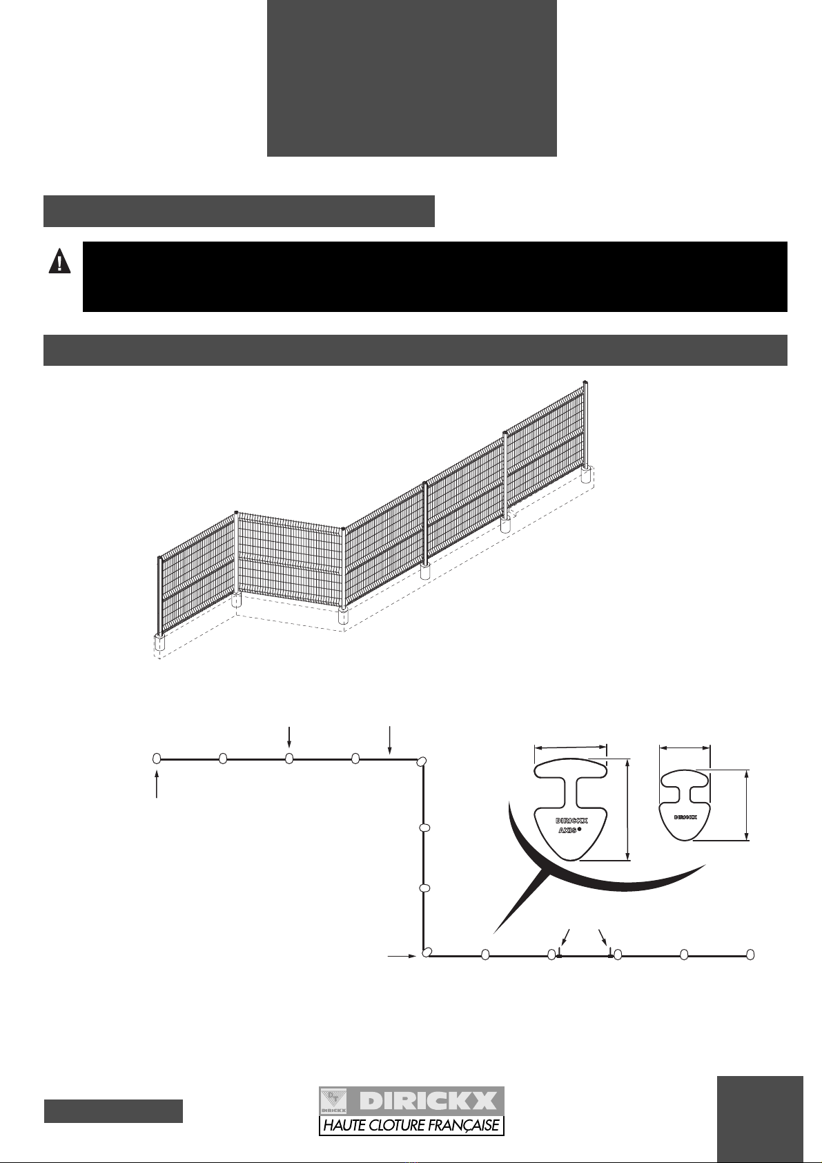
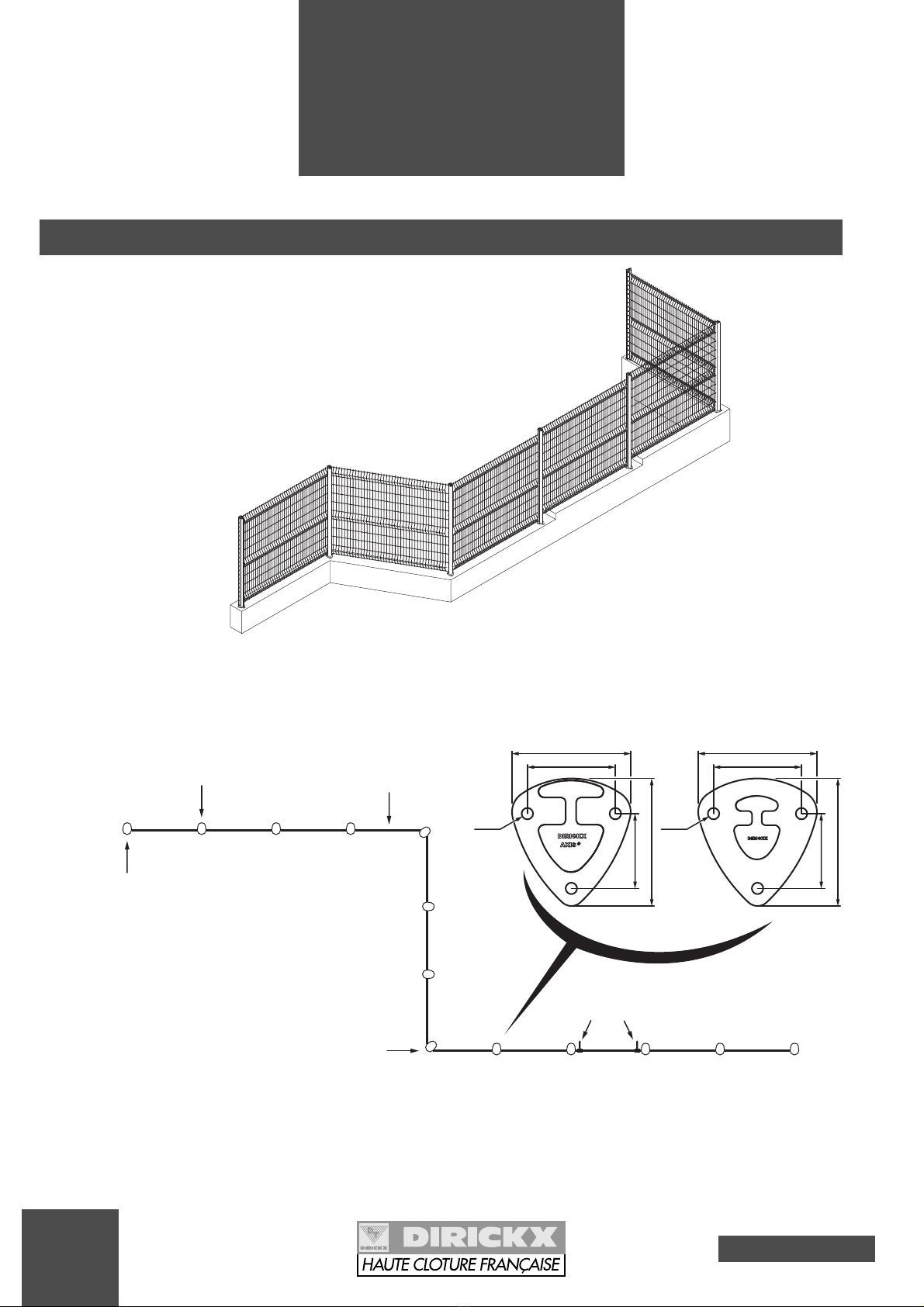
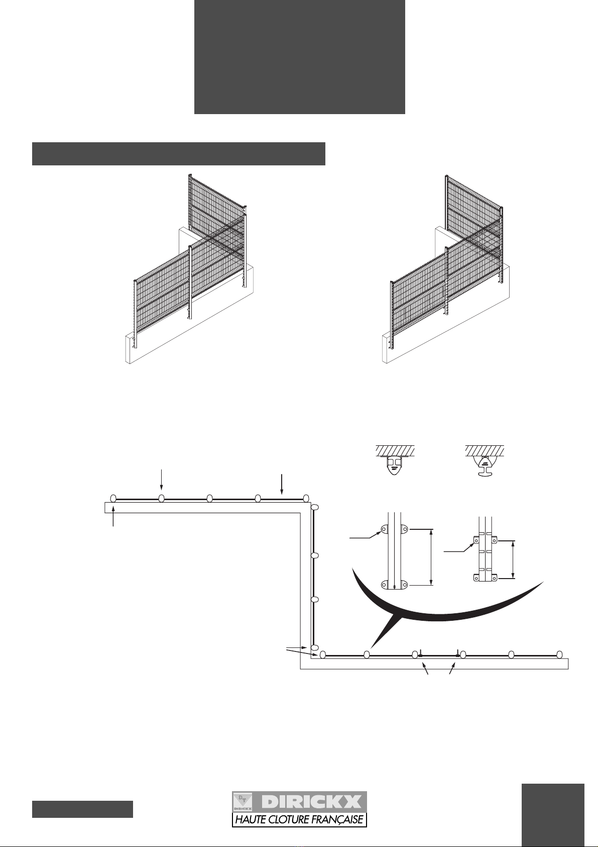
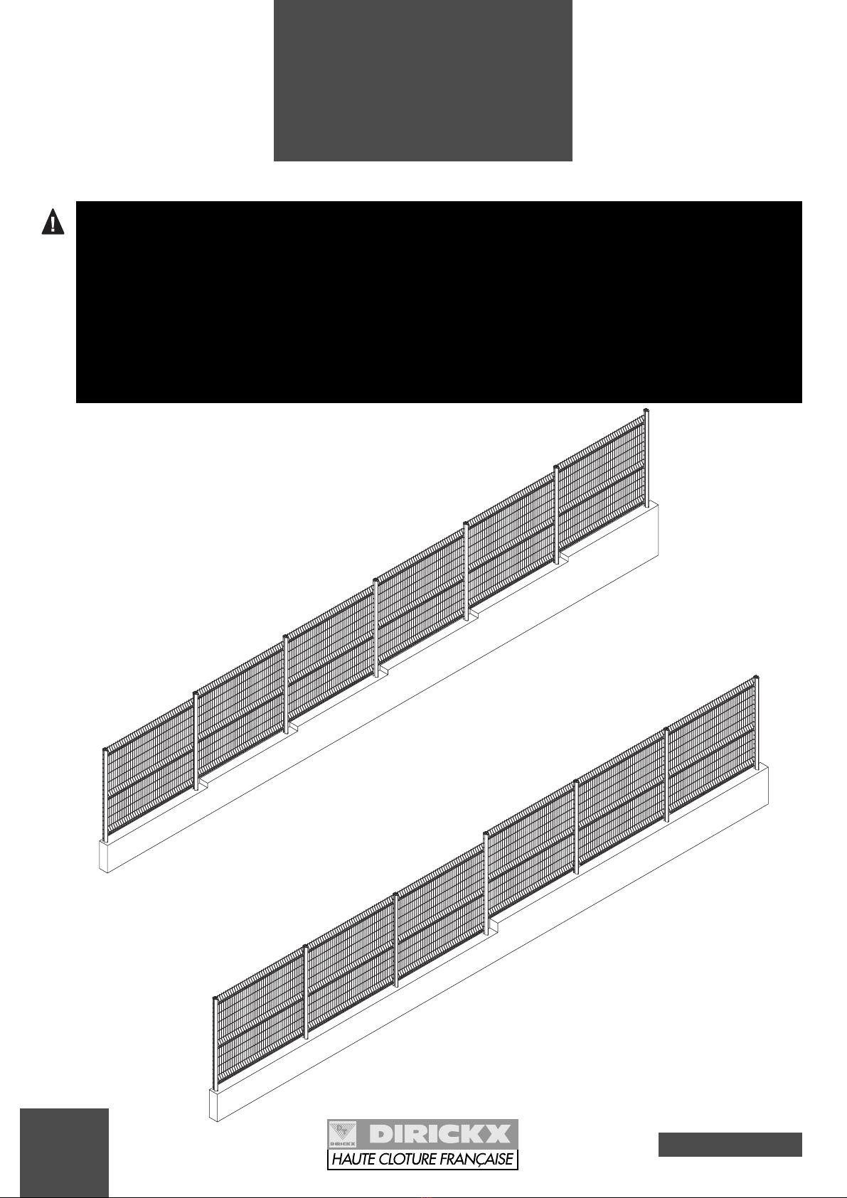
MAKE A STUDY OF THE LIE OF THE LAND BEFORE SETTING:
- if the terrain is sloping, allow for steps by offsetting each panel by 1 or 2 notches, or create
lengthwise steps (where steps are made the posts must be more securely sealed).
- in the corners, turn the posts to the required angle.
- if extension arms are to be used, remove the caps and check whether or not posts have to be
doubled in the corners, by referring to the "AXIS®Design extension arms" notice.
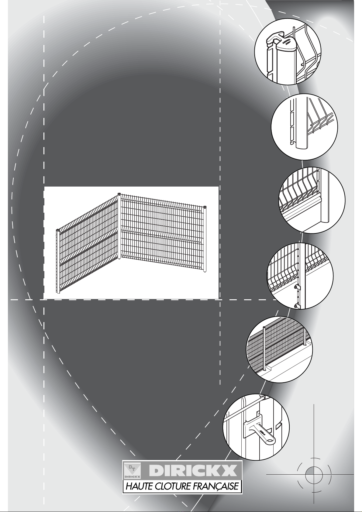
- the panel spikes can be directed downwards or upwards depending on the degree of security
chosen.
2
Ground
constraints
LENGTHWISE STEP
STEP AT EACH PANEL
7
Issue 01 - 05 2003
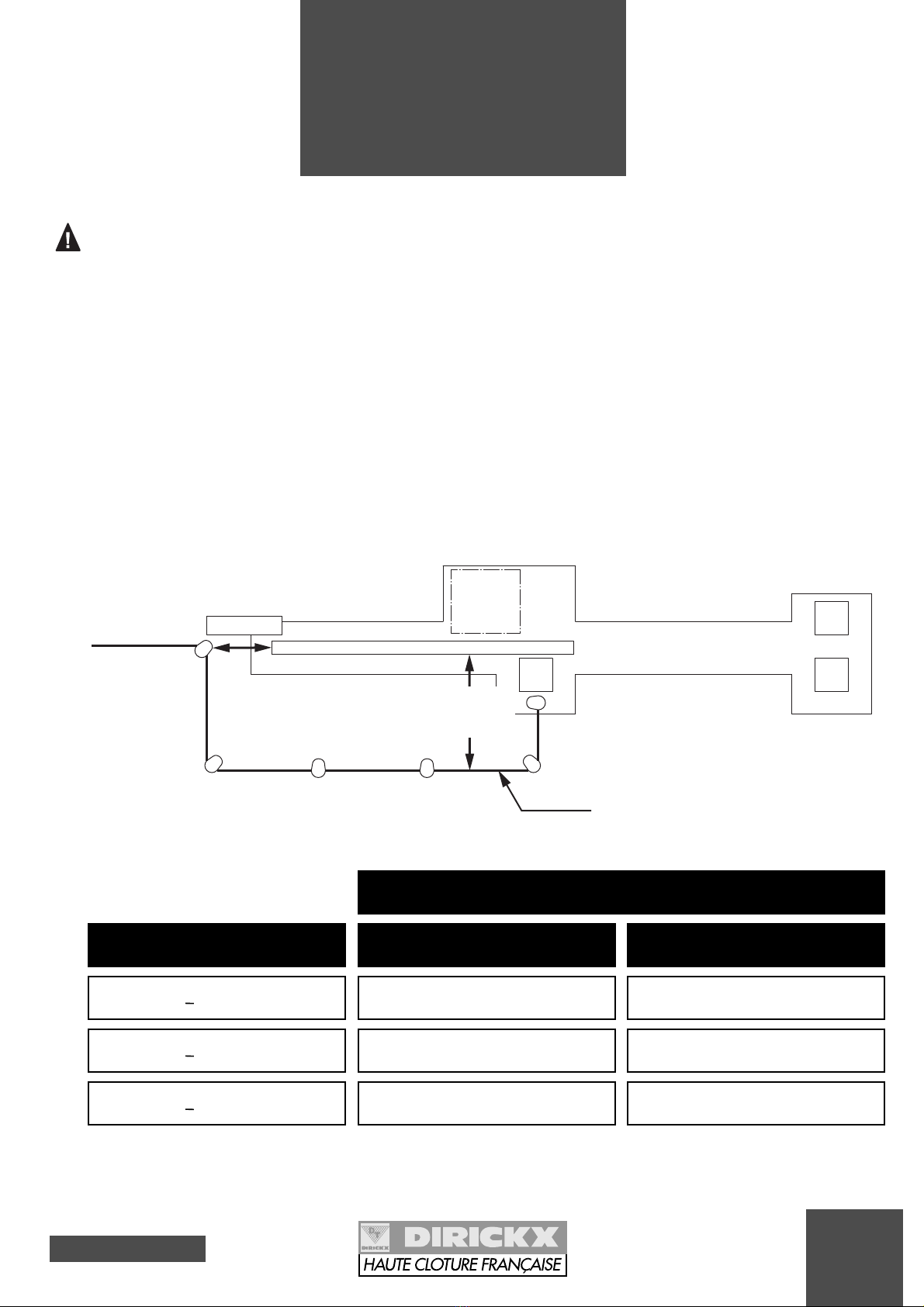
FOR FENCING NEAR A GATE OR AN ACCESS:
** SMALL MESH CAN BE SUPERIMPOSED WITH THE AXIS®PANELS.
* DISTANCE TO BE RESPECTED TO AVOID RISK OF BEING CAUGHT INSIDE.
The backslide zone of tracked sliding and cantileve-
red sliding gates must be protected according to the
NF EN 12635 standard (Gates equipping industrial
and commercial sites and garages - Installation and
utilisation). This standard stipulates that it is obliga-
tory to provide protection against risks of crushing,
shearing and dragging.
Thus, the fence must be set in position at a safe dis-
tance from the moving gate panel (see diagram
below).
This safe distance takes into account the exposed
parts of the human body according to the NF EN 294
standard (safety distances to avoid the upper mem-
bers reaching dangerous areas) and the mesh
dimension of the installed fences along the length of
the gate (see table below).
2
Ground
constraints
SAFE DISTANCE
>120 mm
>200 mm
>850 mm
MESH DIMENSION
BACKSLIDE FENCING
from 20 to 30 mm
from 30 to 40 mm
> 40 mm
PRODUCT EXAMPLES
ARAVIS**
Square mesh**
AXIS®
Inside the site
Passageway
Outside the site
BACKSLIDE
ZONE
GATE PANEL
> 500 mm*
Safety distance
(see table)
Fencing
SETTING IN PLACE
Issue 01 - 05 2003
8
3
Setting for
concreting
AXIS®Design or AXOR®posts
in the ground or on a low wall
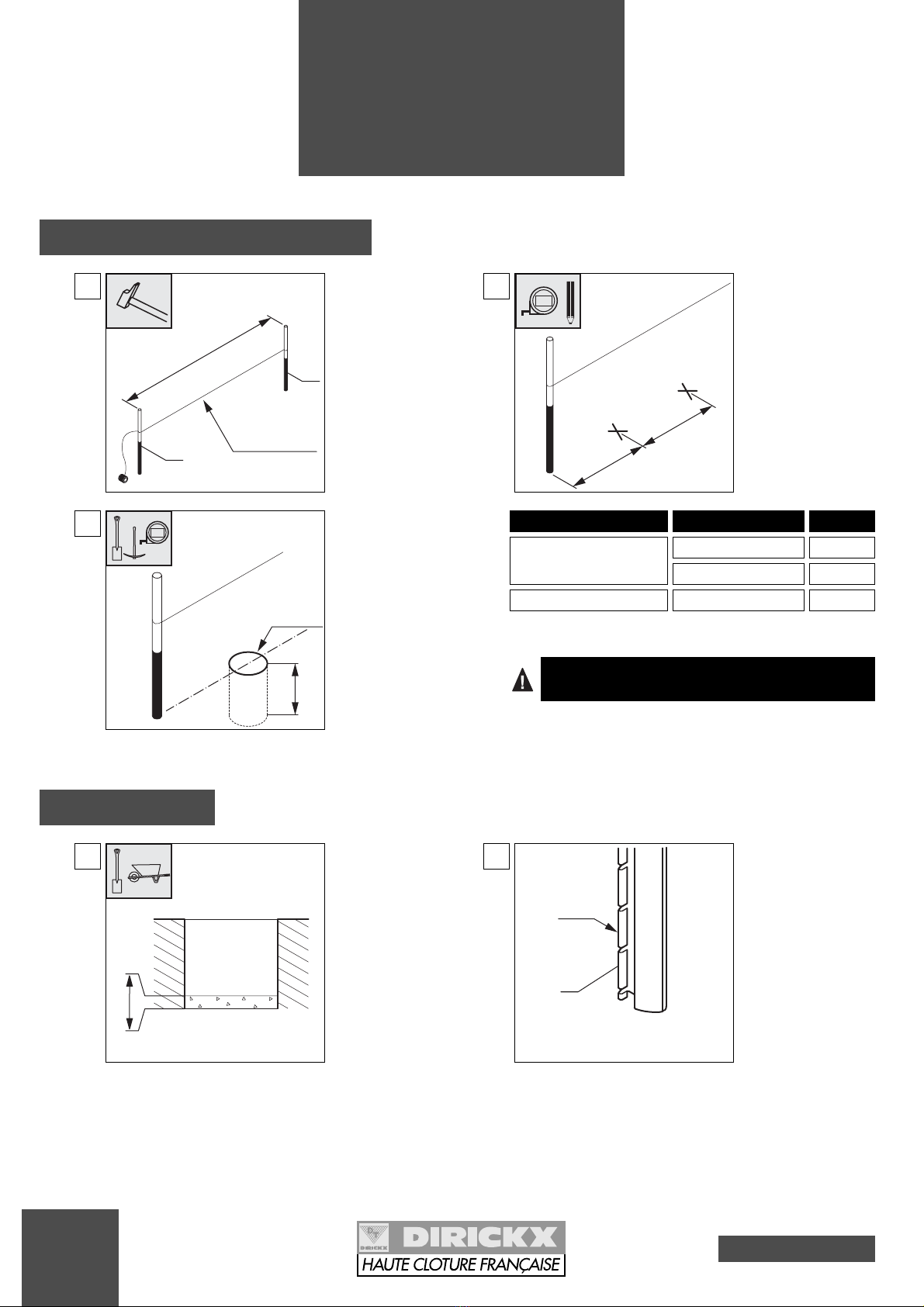
3-1 Preparation - Civil engineering
1
Put the pegs in place
(Ref. 1) every 100 m.
Stretch a line.
100 m
Plumbline
1
1
2
Mark out the post
centres.
Centre Centre
Plumbline
5m
3
Dig holes of ø30 cm
and depth 60 cm mini-
mum.
60 cm
Plumbline
Ø30 cm
5m
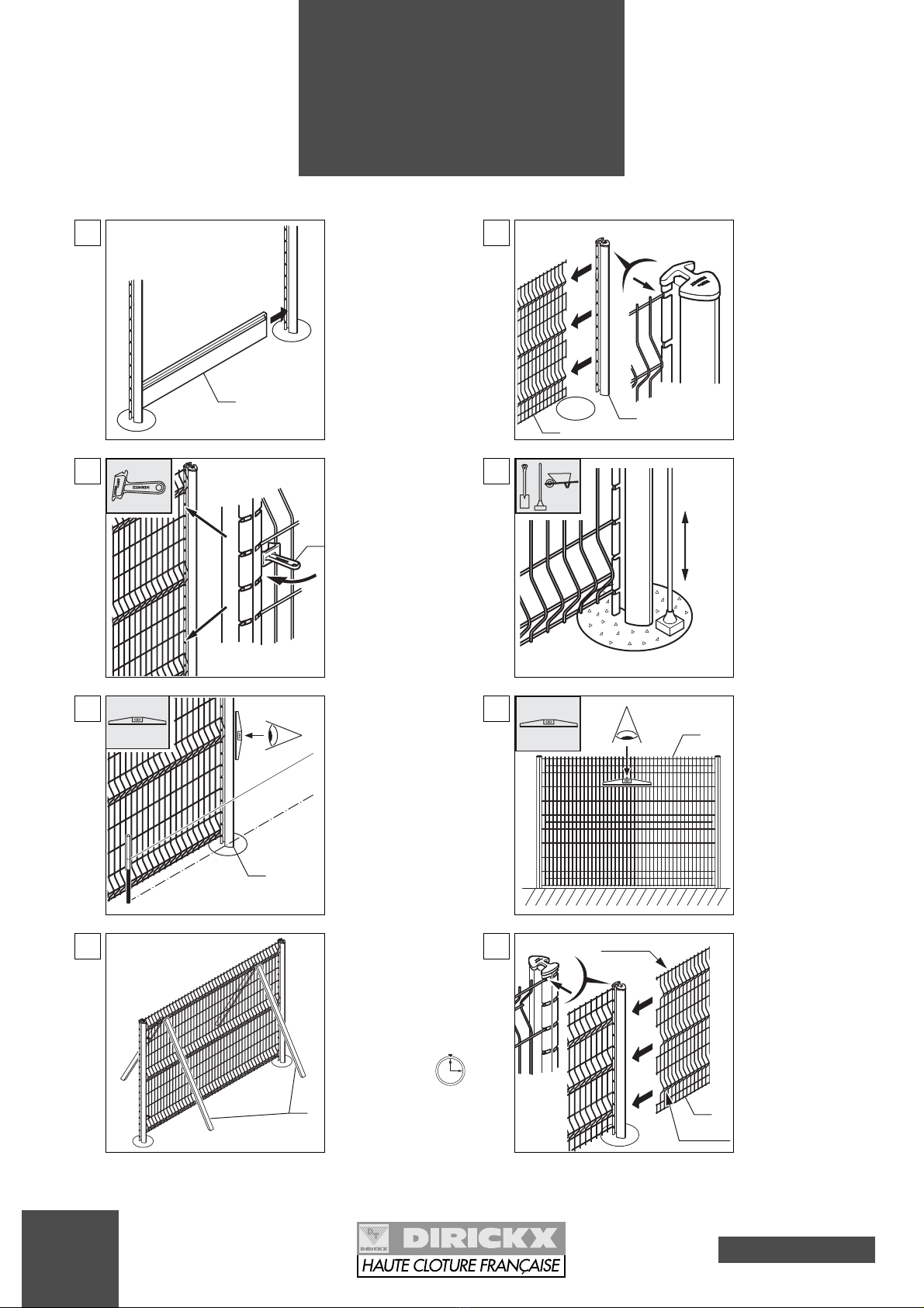
3-2 Installation
1Pour 10 cm of conc-
rete into the bottom
of the hole.
10 cm
T
HE CONCRETE FOR FILLING THE HOLES IS TO BE COMPOSED
OF
250 KG
OF CEMENT
/ M
3
(~ 40
LITRES PER HOLE
).
Mounting with posts
AXIS®Design
AXOR®
AXIS
®
HN < 2,43 m
Panels
Centre
2,536 m
2,371 m
2,510 m
AXIS
®
HN ≥≥2,43 m
AXIS®
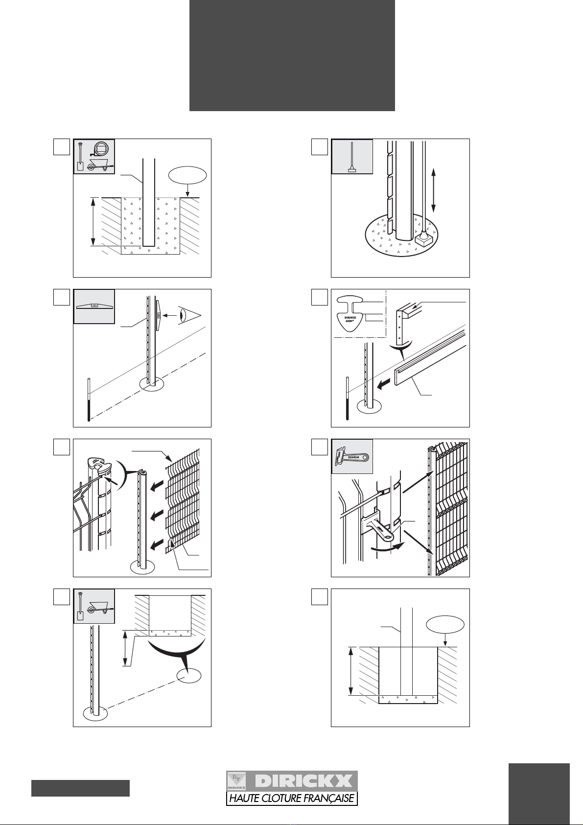
2
Check the mounting
direction of the post
(Ref. 2): the lug is to
be on the side inside
the site.
Lug
INSIDE
THE SITE
OUTSIDE
THE SITE
2
9
Issue 01 - 05 2003
3
Setting for
concreting
AXIS®Design or AXOR®posts
in the ground or on a low wall
5Check the alignment
of the post (Ref. 2).
alignment with
a plumbline
2
6If a kick board is to
be set:
Fix the kick board
(Ref. 3) in the groo-
ve in the post (over-
hang on the external
side).
3
Overhang
7
Attach the first panel
(Ref. 4) (spikes
upwards or down-
wards, crimps on the
side facing the outsi-
de of the site) in the
lugs of the post and
pull to the bottom of
the groove.
Keep the panel ali-
gned throughout the
whole operation.
4
crimps
Spikes
8Set 2 tensioning
tools in position
(Ref. 5).
5
4Ram it down.
9Pour 10 cm of conc-
rete into the bottom
of the second hole.
10 cm
10 Set the second post
(Ref. 6).
X = Sealing length
(see page 20).
X
+0.00
-
6
3Set the first post
(Ref. 2).
Pour the concrete to
fill the hole.
X = Sealing length
(see page 20).
X
+0.00
-
2
5m
Issue 01 - 05 2003
10
3
Setting for
concreting
AXIS®Design or AXOR®posts
in the ground or on a low wall
11 If a kick board is to
be set:
Fix the kick board
(Ref. 3) in the groo-
ve of the second
post.
3
12
Attach the second
post (Ref. 6) onto the
panel (Ref. 4).
46
13 Set 2 tensioning
tools in position
(Ref. 5).
5
14 Pour the concrete
and ram it down.
15 Check the alignment
of the post (Ref. 6).
alignment with
a plumbline
6
16 Check the panel is
level (Ref. 4).
4
17 Set stays* in position
(Ref. 7) on either
side of the panel in
place.
Respect the setting
time: 3 hrs minimum.
*stay: wooden strut
or prop.
7
18
Attach the second
panel (Ref. 8) (spi-
kes upwards or
downwards, crimps
on the side facing the
outside of the site) in
the lugs of the post
and pull to the bot-
tom of the groove.
Keep the panel ali-
gned throughout the
whole operation.
8
Crimps
Spikes
Indice
Altri manuali DIRICKX Recinzioni e cancelli


