DITEC ENTREMATIC AS45 Manuale utente

Installation manual for
panic devices.
(Original instructions)
AS45
IP2042EN - rev. 2012-07-24
DITEC S.p.A.
9ia 0ons. %an¿ - 21042 Caronno Pertusella (9A) - ITA/<
Tel. 02 11 - )a[ 02 014
EN

2
IP2042EN 2012-07-24
INDEX
LIST OF UTENSILS
LIST OF PROFILES AND SEALS
Tape measure
Pencil
Phillips screwdriver
)lathead screwdriver
Scissors
mm Allen Ne\
4 mm Allen Ne\
mm Allen Ne\
mm Allen Ne\
.CP)
mm Allen Ne\for tightening the e[-
panders [18] with special bit
10 mm socNet wrench
Drill
Pliers
Nippers
Saw
/evel
TOPIC PAGE
/ist of pro¿les and seals 2
/ist of utensils 2
AST PANIC SYSTEM
1. AST mobile wing installation 4
2. AST ¿[ed wing installation 10
. AST electrical connections 1
ASME PANIC SYSTEM 17
4. ASME mobile wing installation 18
. ASME electrical connections 24
ASMI PANIC SYSTEM 2
. ASMI mobile wing installation 2
7. ASMI electrical connections 2
100 80 8187
8124 88
800 820 2 8
80 821 0SPAZ14
808 822 417SPAZ4811
All right reserved
All data and speci¿cations have been drawn up and checNed with the greatest care. The manufacturer cannot however taNe an\
responsibilit\for eventual errorsommisions or incomplete data due to technical or illustrative purposes.

3IP2042EN 2012-07-24
AST panic devices are TÜV approved for use with DITEC TEN
and VA/O5model automations.
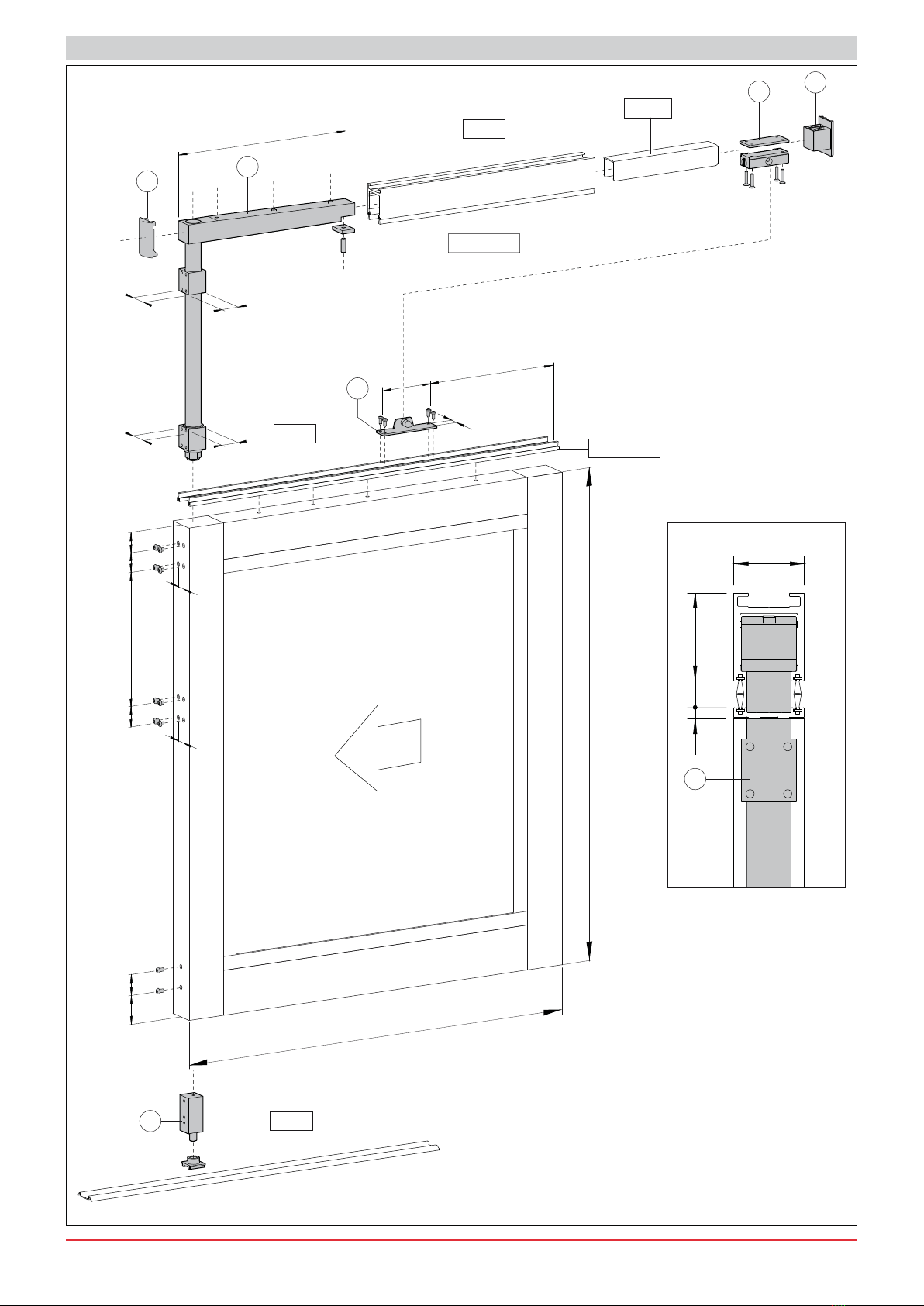
Each carriage installed must be connected to the mobile panic
wing b\at least two fastening points.
The wings to be used are intended as having been built with
DITEC PAM4/ and PAM4M series pro¿les.
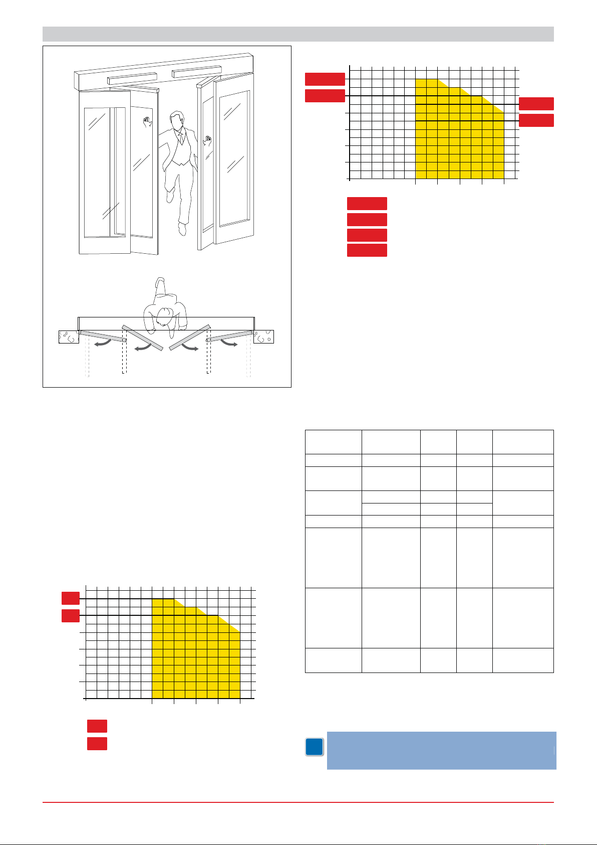
The ma[imum height of the mobile panic wing (+M) must not
e[ceed 2400 mm.
The dimensions (/M) and the ma[imum weight of the door that
can be NnocNed out must compl\with the following graphs for
one and two mobile door automations.
Note: For dimensions and/or weights which are not accounted
Ior in the diagramcon¿rm the IeasiEiOit\oIthe SroMect with our
technicaOcommerciaOoI¿ces
600 8000
0
80
20
40
60
100
120
1000 1200
mm
1400 max
kg 1 wing automation
VALOR L - VALOR P - REX - TEN
VALOR B - VALOR N
MAX
MAX 100
120
AST
600 8000
0
80+80
20+20
40+40
60+60
100+100
120+120
1000 1200
mm
1400 max
kg
TEN
VALOR B - VALOR N
MAX
MAX
MAX
MAX REX
VALOR L - VALOR P
2 wings automation
90+90
70+70
70+70
90+90
100+100
120+120
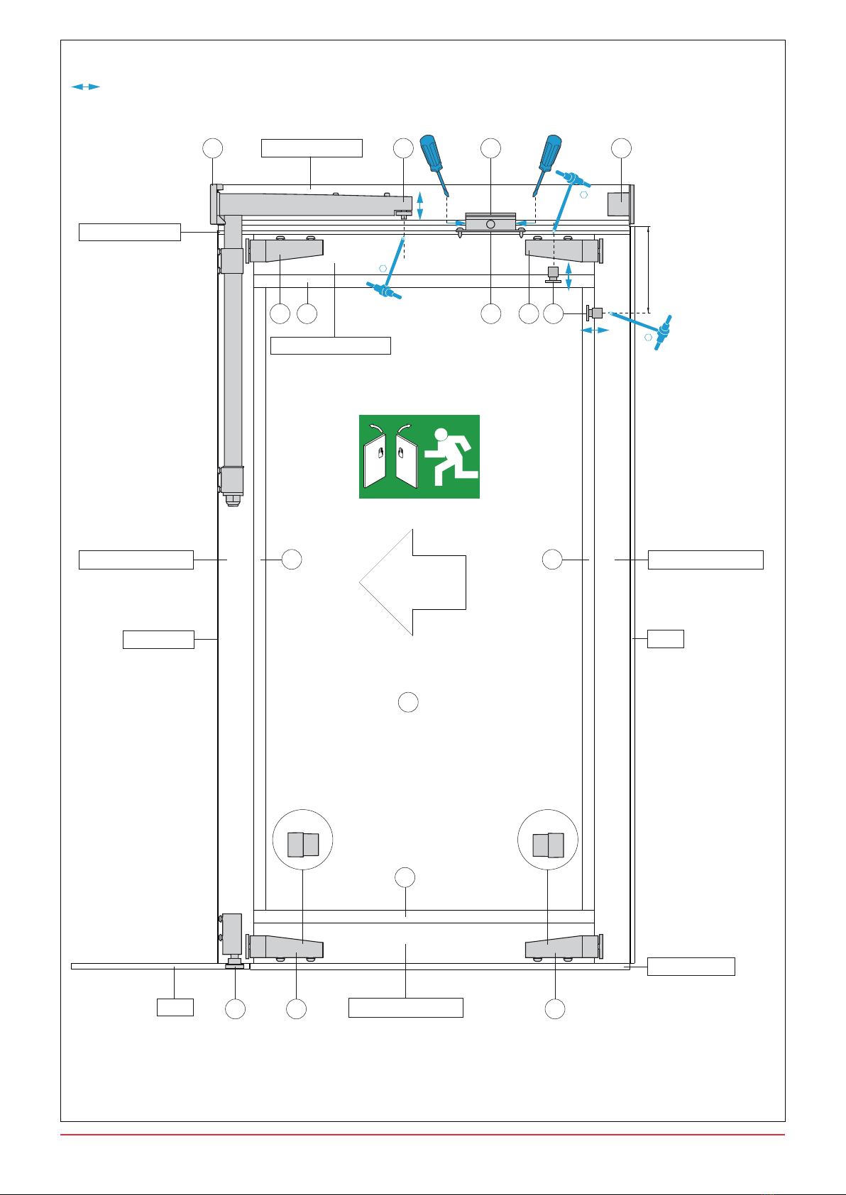
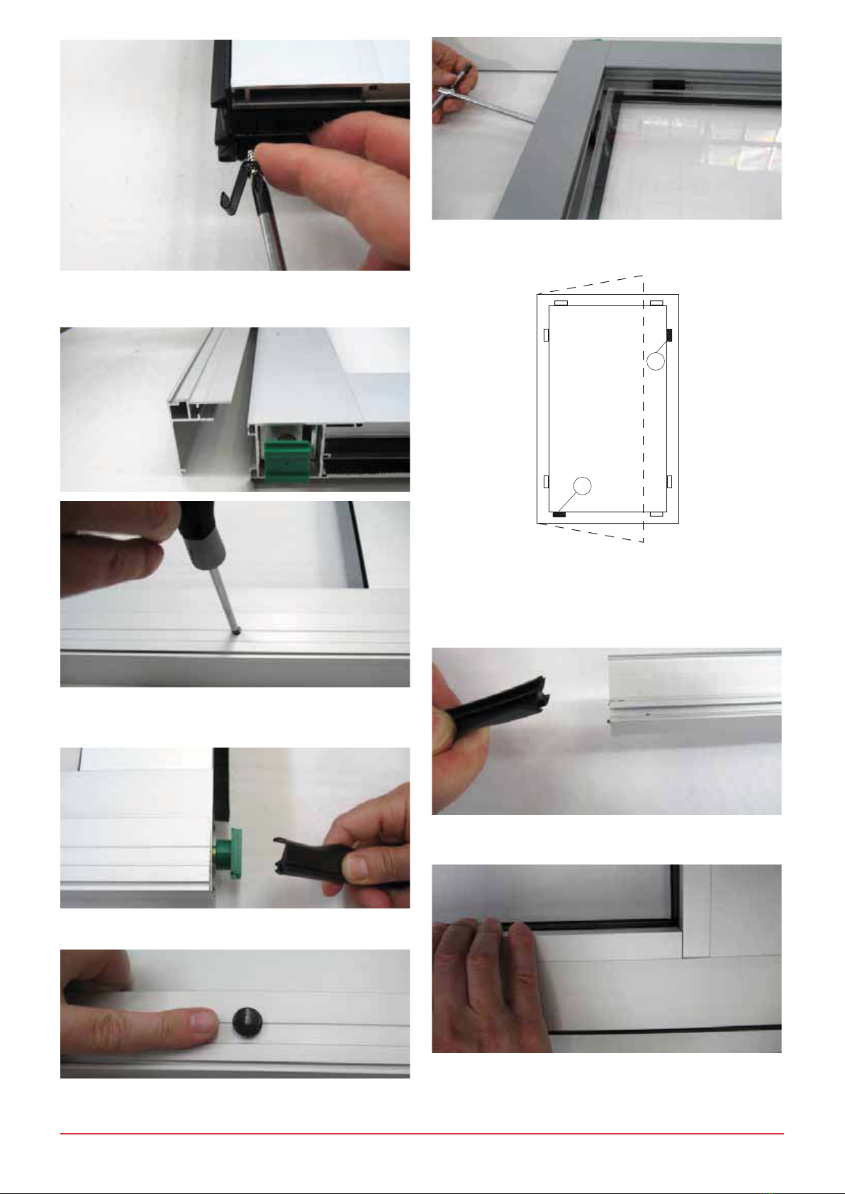
If the width of the mobile panic wing (/M) is greater than 1000
mmadd reinforcement 417(see ¿g. 1)
If the width of the mobile panic wing (/M) is greater than 1200
mmadd reinforcement the third carriage.
If the weight of the mobile panic wing is greater than 0 Ngadd
Nit .AS4to the lower portion (see ref. 1 ¿g. 2).
Note: 2nO\ Ior 3$0/ ,I the weight oIthe door does not e[ceed
Nguse the .,F Nit in the Oower Sart see reI ¿g
The ma[imum height of the ¿[ed panic wing (+)) must not
e[ceed 2400 mm.
The width of the ¿[ed panic wing (/)) must not e[ceed 100
mm and the weight must not e[ceed 100 Ng.
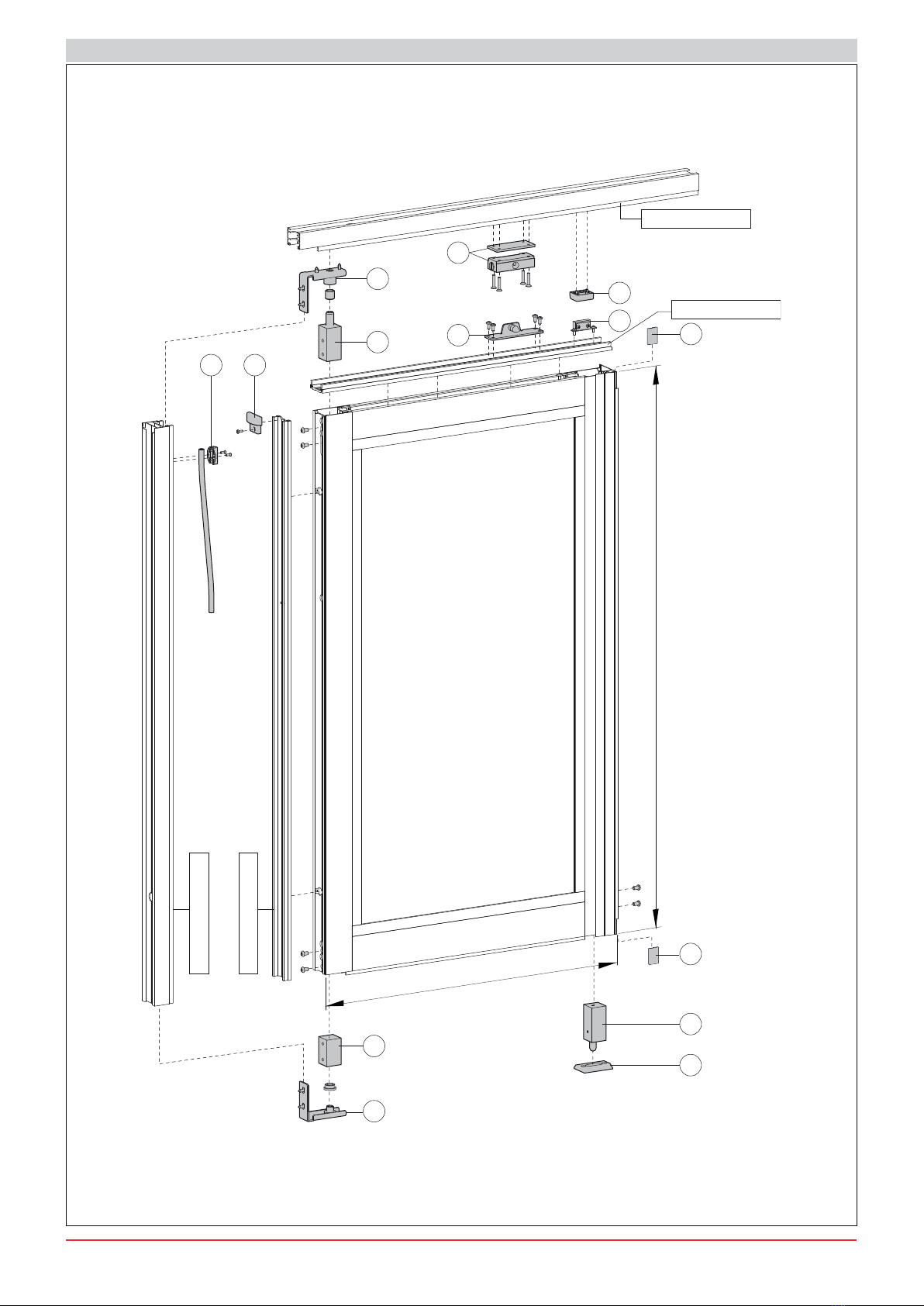
REF. KIT Q.T.
AST1 Q.T.
AST2 SERIE
10KIT AST1 Q.T. PAM4/
1 KAS4AST2 SE5I-
ES
PAM4/
PAM4M
2--4---
7-2
KASM141 PAM4/
PAM4M
KASM24-1
10 KI)41 2 PAM4/
820
24
100
417
SPAZ4811
KASMG14
KASMN14 12
PAM4/
PAM4M
1-11-12-1-
14-1-1-
17-18-1-
20-21-22-
2-24-2
KAST1A4) 12
PAM4/
PAM4M
27 1CE/P522
PAM4/
PAM4M
Note: 8se .it &(/35 iI\ou wish to instaOO the ShotoceOOs that
detect the Sresence oISeoSOe and oEMects in the Sassage cham
Eer see reI Sag
$ttention: 8se the 3$0/ $67 or 3$00 $67 manuaOs
to determine the cut measurements, the kits required and
the required Sro¿Oe SreSarations
$ttention:
8
se the 3$0
/$
6
7or 3$0
0$
6
7manuaO
s
t
o determine the cut measurements, the kits required an
d
t
he required Sro
¿
Oe SreSarations
i

4
IP2042EN 2012-07-24
1600230x30
3924
HM
717 56
45
4
SPAZ4811
3820
*4173
SPAZ4811
6
3
57
1930330303040
4xØ6,54xØ6,52xØ6,5
150
340
35 33
98
16
24
4xØ4,2
24
35 33
600< LM < 1400
3
1. AST MOBILE WING INSTALLATION
() Onl\with /M !1000
)ig. 1

5IP2042EN 2012-07-24
63820+SPAZ4811
1 8
8
9
8
8
4 1
3 7
1
5
3808 (*3821)+3839 3808 (*3821)+3839
3805+SPAZ14
3831+3838 3837
1600 1
*10
23800 (*3599)+3839
3813 (*3822)+3839
** **
*10
26
3924+SPAZ4811
6
6
4
160
() PAM4/
() Onl\with mobile wing !0 Ng
Adjustments to be performed during installation
)ig. 2

6
IP2042EN 2012-07-24
1.1 Insert the seal 8 into the PAM4M pro¿les 800808
and 81or else the PAM4/ pro¿les 821 and 822as
shown in the diagram.
1.2 Shorten the seal to the si]e of the pro¿le.
1.Insert detail [1] into the PAM4M pro¿les 800 and 81
or else the PAM4/ pro¿les and 822and fasten it as
shown in the diagram.
1.4 -oin the vertical pro¿les with the hori]ontal pro¿les and fa-
sten them as shown in the diagram.
Note: :ith 3$0/ Sro¿Oes, the gOass >@ must Ee inserted
when Moining the YerticaOand hori]ontaOSro¿Oes
7he gOass suSSort sSacers must Ee SroSerO\ aSSOied to the Iour
sides and must Ee adMusted as shown in SaragraSh
1.)asten pro¿le 80to the lower portion of the wingas
shown in the diagram.
1.Insert the brushes SPAZ14 as shown in the diagramand
blocNthem to prevent them from sliding.

7IP2042EN 2012-07-24
1.7 Insert detail [2] into the lower portion of the wing and fasten
it as shown in the diagram.
1.8 Insert detail [] into the upper portion of the wingas shown
in the diagram.
1.)asten detail [] b\tightening the eight fastening screws
as shown in the diagram.
1.10 Insert the brush SPAZ4811 into pro¿les 24 and 820as
shown in the diagram.
1.11 )asten pro¿le 24 to the upper portion of the wingas
shown in the diagram.
1.12 )asten detail [4] to pro¿le 24as shown in the diagram.
Note: %e sure to take note oIthe wing¶s oSening direction
1.1Trim the brush SPAZ4811 where it connects with detail
[]as shown in the diagram. Note: Be sure to take note of the
wing¶s oSening direction
1.14 Insert pro¿le 820 into detail []as shown in the dia-
gram.

8
IP2042EN 2012-07-24
1.1)asten detail [] to pro¿le 820as shown in the dia-
gram.
Note: during the instaOOation of the ¿[ture, in order to oEtain the
SroSer hori]ontaOSosition of the moEiOe Sanic wing, Ooosen the
fastening screws and adMust the screw shown in detaiO>@, as
shown in the diagram
1.1If the width of the mobile wing is greater than 1000 mm
insert reinforcement 417into pro¿le 820as shown in the
diagram.
1.17 Insert detail [] into pro¿le 820as shown in the diagram.
Note: Be sure to take note of the wing¶s oSening direction
1.18 Position detail [] in correspondence to detail [4] and fa-
sten it as shown in the diagram.a.
Note: during the instaOOation of the ¿[ture, in order to oEtain the
SroSer Ereakawa\strength for the moEiOe wing, use the OateraO
screws to adMust detaiO>@, as shown in the diagram
1.1Insert detail [] into pro¿le 820 near detail []as shown
in the diagram.
1.1 Insert the seal 87 onto the PAM4M pro¿le 808or else
the PAM4/ pro¿le 821as shown in the diagram.
$ttention: 2rient seaO as indicated in the ¿[tures manuaO
0ake a hoOe in the seaOthat corresSonds with the thickness
adMustment of the Sush gOass >@ as shown in the Sicture
1.21 Insert detail [7] into pro¿le 820as shown in the dia-
gram.
$ttention: 2rient detaiO>@ in the same manner as seaO

9IP2042EN 2012-07-24
1.22 Attach the supplied hooNto the lower part of the wing
as shown in the diagramin order to prevent seal 87 from
sliding.
1.2Attach pro¿le 81 to the PAM4M pro¿le 808or else to
the PAM4/ pro¿le 821as shown in the diagram.
1.24 Insert seal 88 into pro¿le 81as shown in the dia-
gramand blocNit to prevent it from sliding.
1.2Close the visible holes with the supplied capsas shown
in the diagram.
1.2:ith PAM4M pro¿lesinsert the glass [] into the mobile
wingas shown in the diagram.
A
A
1.27 Set the glass spacers [A]shown in the diagramso that
the\provide proper support.
NB: when instaOOing the ¿tting, adMust the Sush gOass sSacers
>@ as shown in the Sicture , for the moEiOe door wing to reach
the hori]ontaOSosition.
1.28 :ith PAM4M pro¿lesinsert the seals into the glass-blo-
cNing pro¿les [8]as shown in the diagram.
1.2:ith PAM4M pro¿lesinsert the glass-blocNing pro¿les
[8] onto the mobile wing until the\clicN as shown in the dia-
gram.

10
IP2042EN 2012-07-24
2. AST FIXED WING INSTALLATION
3809 + SPAZ4811
3924 + SPAZ4811
12
11
24
13
20
HM
LM
3924+SPAZ4811
3809+SPAZ4811
14 16
22
23
15 13
1719
21
)ig.
Altri manuali DITEC Recinzioni e cancelli


