Divio NRP1482 Manuale utente

Content
ii
C
ONTENTS
Chapter 1: Product Introduction
Overview ............................................................................................ 1
Key Features.................................................................................... 1
Hardware Specifications ....................................................................... 2
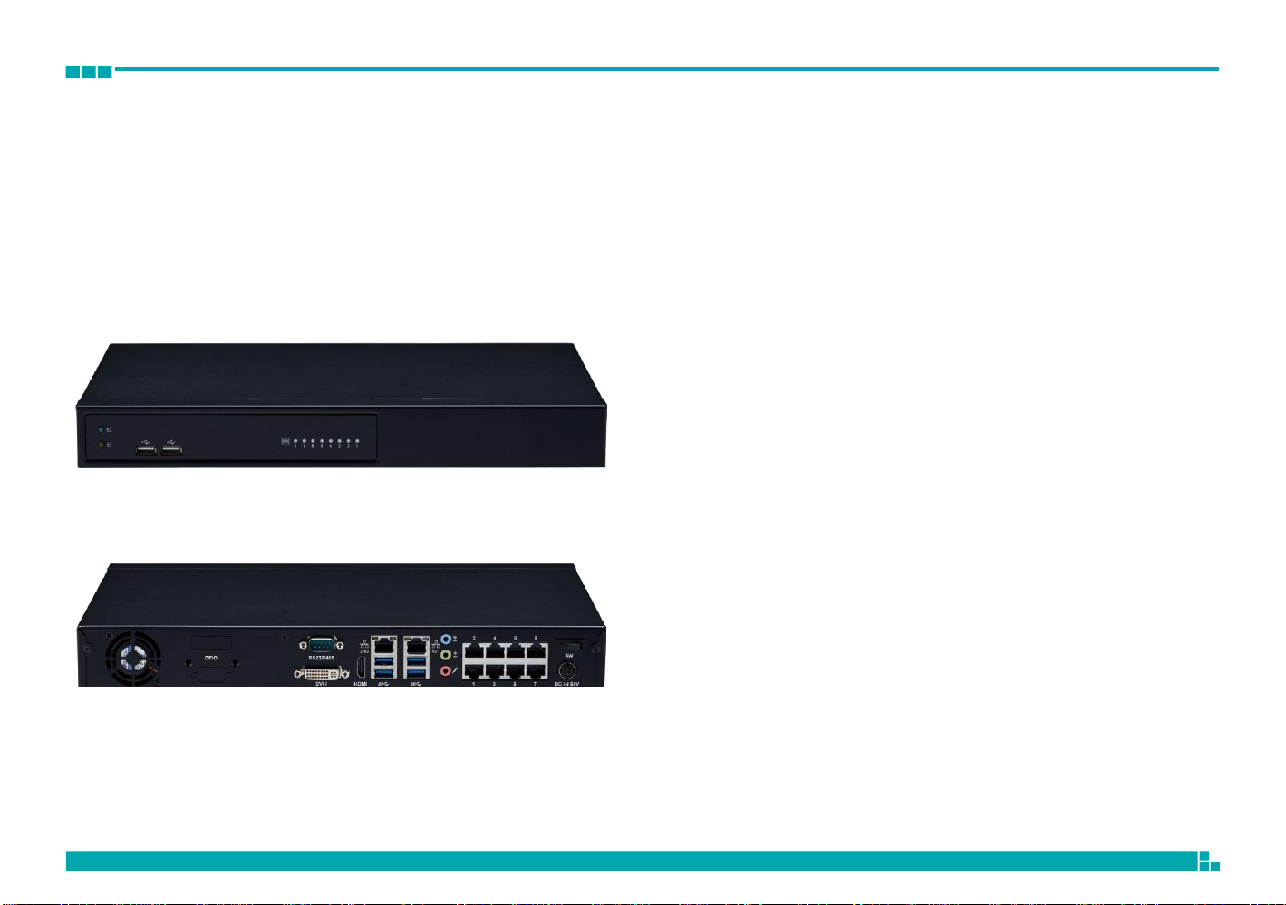
Knowing Your NRP1482 Series .............................................................. 3
Front Panel ...................................................................................... 3
NRP1482 Rear Panel ......................................................................... 4
Mechanical Dimensions......................................................................... 5
Mechanical Dimensions......................................................................... 6
Mechanical Dimensions......................................................................... 7
Chapter 2: Jumpers and Connectors
Before You Begin ................................................................................. 8
Precautions ......................................................................................... 8
Jumper Settings................................................................................... 9
Locations of the Jumpers and Connectors ..............................................10
Jumpers.............................................................................................11
Clear CMOS.....................................................................................11
Connector Pin Definitions.....................................................................12
54V Power-in Connector (Outside).....................................................12
PoE LAN 8 Ports RJ45 Connector .......................................................12
GPIO Connector ..............................................................................13
System Fan.....................................................................................14
USB2.0 Connector ...........................................................................14
HDD/PWR LED Wire.........................................................................15
SATA Connector ..............................................................................15
SATA Connector........................................................................ 16
SATA Power Connector .............................................................. 16
Audio Connectors...................................................................... 17
Power SW Connector................................................................. 17
COM Port Connector .................................................................. 18
Debug Port Connector ............................................................... 18
LAN1 Connector and USB 3.0 Ports ............................................. 19
LAN2 Connector and USB 3.0 Ports ............................................. 19
SPI BIOS Update Connector ....................................................... 20
HDMI Connector ....................................................................... 20
DVI-I and RS485 Connector ....................................................... 21
POE 8 Ports LAN LED Connector ................................................. 22
M.2 B Key Connector ................................................................. 23
PoE Switch Action Guidance .......................................................... 24
PoE Switch Connecter Define (Rear IO) ....................................... 24
PoE Switch LED Indicator Status (Front Side)................................ 24
PoE Switch Deployment ............................................................. 24
Block Diagram.............................................................................. 26
Chapter 3: System Setup
Removing the Chassis Cover.......................................................... 27
Installing the 3.5” HDD ................................................................. 28
Installing the 2.5” SSD/HDD .......................................................... 34
Tightening Cable Guidance For 2.5” SSD/HDD ................................. 37
Installing M.2 SSD ........................................................................ 39
Installing Memory SO-DIMM (Use DDR4 SO-DIMM).......................... 41

Preface
iii
Chapter 4: BIOS Setup
About BIOS Setup.........................................................................43
When to Configure the BIOS ..........................................................43
Default Configuration ....................................................................44
Entering Setup .............................................................................44
Legends.......................................................................................44
BIOS Setup Utility .........................................................................46
Main ....................................................................................46
Advanced .................................................................................47
Chipset.....................................................................................56
Security....................................................................................61
Secure Boot ..............................................................................62
Boot.........................................................................................62

Chapter 1: Product Introduction
1
CHAPTER 1: PRODUCT INTRODUCTION
Overview
Key Features
▪Intel Celeron J6412, Quad Core 2.0GHz
▪Max. 32GB DDR4 supported
▪
Dual display of HDMI and DVI-I
▪1 x 3.5” SATA HDD
▪
1 x 2.5” SATA HDD or SSD/1 x M.2 2242 Key B SATA III
(select either one)
▪
1 x 10/100/1000 Intel
®
Ethernet
▪
1 x 2.5G Intel Ethernet
▪
8 x 10/100 PoE (120W max PSE)
▪Support TPM 2.0 onboard
▪Support eMMC onboard (option)

Chapter 1: Product Introduction
2
Hardware
Specifications
CPU Support
▪
Intel 8
th
Gen Intel
®
Celeron
®
J6412, Quad Core, 2.0GHz base frequency,
2.6 GHz burst frequency (compatible with other Intel 8
th
Gen Intel Atom
®
(Elkhart Lake) processor X Series and Intel
®
Celeron
®
J Series)
Main Memory
▪Dual channel DDR4 3200 MHz SDRAM, max. 32GB
I/O Interface-Front
▪2 x USB 2.0 ports
▪
Power & HDD status LED
▪
PoE 8 ports status LED
I/O Interface-Rear
▪
2 x RJ45 (1 x 1GbE + 1 x 2.5GbE)
▪4 x USB 3.1 Gen1 ports
▪
1 x HDMI 2.0b (supports max. resolution 4096 x 2160 @ 60Hz)
▪
1 x DVI-I
▪
1 x UART port (RS-232/485 setting from BIOS)
▪1 x Min-in & 1 x Line-Out & 1 x MIC
▪
Power on/off switch
▪
54V DC-IN jack (4-pin)
▪
8 x Ethernet PoE port
-
802.3af/at compliance with total 120W max (PSE)
-
802.3af support 8 ports @ 15W
-
802.3at support 4 ports @30W
▪1 x 4DI/2DO (relay type) terminal block or 4DI/4DO GPIO DB15 port
(option)
Storage
▪1 x 3.5” SATA HDD
▪
1 x 2.5” SATA HDD or SSD/1 x M.2 2242 Key B SATAIII (select either one)
▪1 x eMMC 32GB (option)
Power Input
▪Adapter 54V/3.34A 180W
Dimensions
▪
360mm (W) x 49mm (H) x 224.5mm (D)
Environment
▪
Operating Temperature:
Ambient with air flow: 0°C to 40°C
▪
Storage temperature: -20°C to 70°C
▪
Relative humidity: 10% to 90% (non-condensing)
Certifications
▪
CE approval
▪FCC Class A
▪UL 62368 compliance

Chapter 1: Product Introduction
3
Knowing Your NRP1482 Series
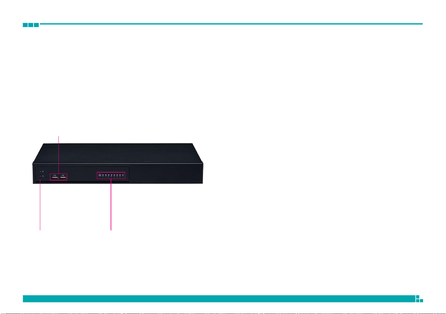
Front Panel
LED Indicators
Indicates the power status of the system.
Indicates the status of the hard drive.
Dual USB Ports
Used to connect USB 2.0 devices.
PoE LAN LED Indicators
Indicates the status of the LAN ports.
2x USB 2.0 Ports
LED Indicators PoE LAN LED Indicators

Chapter 1: Product Introduction
4
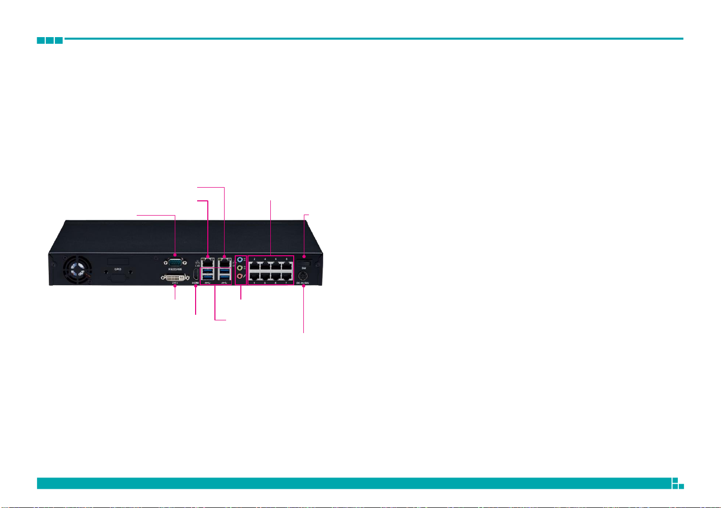
NRP1482 Rear Panel
1x COM (RS232/RS485) Port (BIOS Support)
Supports RS232 and RS485 compatible serial devices.
DVI-I
Used to connect a digital LCD panel.
1.0 GbE RJ45
2.5 GbE RJ45
8x PoE LAN Ports RJ45 Connector
HDMI
Used to connect a high-definition display.
1.0 GbE RJ45/2.5 GbE RJ45
1x COM (RS232/RS485) Port
DVI-I
Audio Connectors
1x PWR SW
Used to connect the system to a local area network.
4x USB3.0 Ports
Four USB ports to connect the system with USB 3.0 devices.
Audio Connectors (Line in/Line out/MIC in)
Line in: Receives audio signal input
Line out: Provides audio signal output
HDMI 4x USB3.0 Ports
54V DC Input
MIC-in: Used to connect an external microphone
8x PoE LAN Ports RJ45 Connectors
Enables communication among network clients and delivers power using
the same RJ45 to PoE-enabled edge devices.
Power Switch
Press to power on the device.
54V DC Input
Used to plug a DC power cord.

Chapter 1: Product Introduction
5
224.50
Mechanical Dimensions
Rackmount Model
1
366.00
360.00
192.80
3.00
28.70
44.00
465.00
482.80
16.00
6.00
6.00

Chapter 1: Product Introduction
6
224.50
360.00
126.00
67.50
Mechanical Dimensions
Desktop Model
360.00
44.00
49.00
287.80
36.10

Chapter 1: Product Introduction
7
Mechanical Dimensions
Wallmount Model
360.00
0
60.00
160.00
8.20
60.00
50.50
68.50
373.80
387.80
44.
00
50.0
Indice
Manuali Sistema di sicurezza popolari di altre marche

EDM
EDM Solution 6+6 Wireless-AE Manuale utente

Highway Safety Group
Highway Safety Group EA401 Manuale utente

Siren
Siren LED GSM Manuale utente

Detection Systems
Detection Systems 7090i Istruzioni per il montaggio

Se-Kure Controls
Se-Kure Controls MicroMini SK-4841 Manuale utente

Siemens
Siemens FDM273 Manuale utente