DIY-Thermocam V2 Manuale utente

Revision 5 from 12.09.2017
1.
• To assemble the device, you need the following tools: A soldering iron, some
solder, a cutting pliers, a nippers, a screwdriver and a multimeter
• At the moment, the following versions of the FLIR Lepton sensor are supported:
2.0 (80x60), 2.5 (80x60 radiometric) & 3.0 (160x120)
• If you have the choice between multiple soldering tips, use the smallest one
• In case you have a soldering station with adjustable temperature, use around 400
- 450 degree celcius
• Catch the PCB, the microcontroller and one of the two pin header strips
• Cut the header strip with a cutting pliers into the following pieces: 2 x 15, 1 x 5 and
3 x 1
DIY-Thermocam V2 Assembly Guide
Page 1DIY-Thermocam V2 Assembly Guide
2.
• Plug the microcontroller into the header pieces
• One of the three single header should be placed in the hole labeled VUSB, do not
forget it
• Put the microcontroller with the headers into the PCB and make sure they sit tight
• Solder the pins on top of the microcontroller
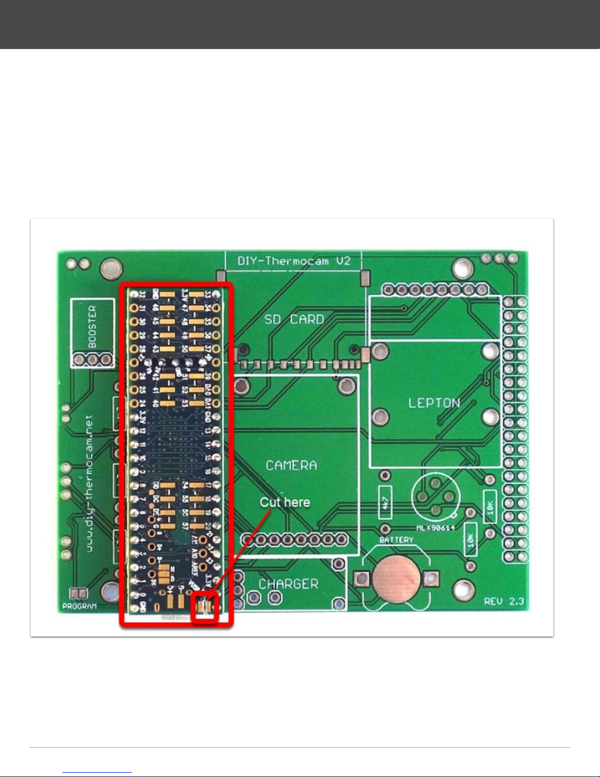
• Cut the trace between VUSB and VIN on the microcontroller with a sharp knife
DIY-Thermocam V2 Assembly Guide
Page 2DIY-Thermocam V2 Assembly Guide

3.
• Turn the PCB around, make sure the microcontroller still sits tight
• Solder the pins on the bottom
• Cut the pins short with cutting pliers, right above the solder points you just made
• Re-solder the pins to make sure they are really connected well to the PCB
DIY-Thermocam V2 Assembly Guide
Page 3DIY-Thermocam V2 Assembly Guide

4.
• Attach the SD card slot to the PCB by soldering the four points on the edges first,
then the data pins on the bottom side
• Put the 8GB micro SD card into the SD adapter
• Put the adapter into the SD card slot
DIY-Thermocam V2 Assembly Guide
Page 4DIY-Thermocam V2 Assembly Guide

5.
• Remove the wifi shield from the backside of the visual camera module
• Push the two female sockets on the two sides alternating to the left and right, until
they drop off
• It's required to break those pieces off, otherwise the module will not fit later
• Use the 8-pin female header socket to bend the 8-pin male header on the bottom
of the module into a straight position
DIY-Thermocam V2 Assembly Guide
Page 5DIY-Thermocam V2 Assembly Guide

6.
• Use two of the M2 x 10 bolts and put them though the holes in the PCB
• On the left bolt, put one of the M2 x 3.5mm distance spacers, on the right bolt one
of the M2 x 3.0mm spacer, take care you choose the right length
• Put the visual camera module on top of the bolts, push the header into the PCB
and save it with two M2 plastic nuts
• Use the remaining M2 x 3.5mm spacer and put between the module and the PCB
on the left position marked, then use a M2 x 3.0mm spacer and put it on the right
side
• Push the module against the PCB, then solder the 8-pin header on the backside
and cut the pins short with cutting pliers
DIY-Thermocam V2 Assembly Guide
Page 6DIY-Thermocam V2 Assembly Guide

7.
• Remove the plastic part from the angled male pins with your hand or a nippers
• Bend the 2-pin header alternating to the left and the right, until it drops off
DIY-Thermocam V2 Assembly Guide
Page 7DIY-Thermocam V2 Assembly Guide

8.
• Grab the 8-pin right-angle female header and put it into the PCB
• Use two M2x10 bolts and put one of the 3.0mm black spacers on top of each
• Plug the Lepton board into the socket and through the two bolts, then save it with
two plastic nuts
• Pick up two more M2x10 bolts and put them into the empty holes on the top, then
save them with plastic nuts
• Use two more smaller black spacers and put them between the PCB and the
Lepton module on the marked position, as they do not fit on the bolts
• Solder the female header to the PCB and cut the pins short with cutting pliers
DIY-Thermocam V2 Assembly Guide
Page 8DIY-Thermocam V2 Assembly Guide

9.
• Solder the step-up converter to the PCB by using a 3 pin strip
• Solder the four 4.7k resistors (the smaller ones) to their position on the PCB
• Solder the two 10k resistors (bigger ones) to their position right to the spot sensor
• Solder the charging module to the PCB by using a pin strip together with four
single ones
• Cut the pins short on the backside with cutting pliers
• Solder the coin cell battery holder to the PCB
DIY-Thermocam V2 Assembly Guide
Page 9DIY-Thermocam V2 Assembly Guide

10.
• Check your FLIR Lepton version: Lepton2.0 (80x60, non-radiometric), Lepton2.5
(80x60, radiometric), Lepton3.0 (160x120, non-radiometric) and skip this step 10 if
you have the Lepton2.5
• Catch the MLX90614 single-point infrared sensor and plug it into the board, make
sure the little indicator matches the mark on the PCB
• Solder one pin first on the backside, then push the sensor against the board while
heating the solder on the same pin to make sure that the sensor is really soldered
flat to the board
• Solder the remaining three pins on the backside
• Cut the pins short with a cutting pliers
DIY-Thermocam V2 Assembly Guide
Page 10DIY-Thermocam V2 Assembly Guide


